Film, chemicals and paper aren’t cheap and a budget for some studio lights is non existant.
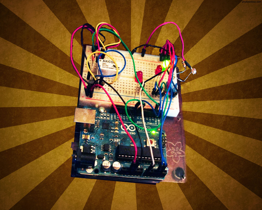
So, I decided to, with the help of my trusty arduino, create my own sync controller to use with disposable camera flash circuits.
By using a photoresistor the arduino can sense when the flash from your camera (master) is triggered and then trips the relay activating the disposable flashes (slaves). Since every environment has a different ambient light level I incorporated a potentiometer to adjust the threshold of light that will trigger the relay. I also added a push button to trip the flash bypassing the photoresistor altogether (this is still a bit buggy and does not always work).
Step 1: Gather The Materials
1 – Arduino (I have the Uno)
2 – 5mm Red LED’s
1 – 5mm Green LED
1 – 10k ohm resistor
1 – 2.2k ohm resistor
1 – Transistor (P2N222AG) (TO92)
1 – Diode (1N4001)
1 – Potentiometer (10k)
1 – Relay (5v DPDT)
1 – Push Button
1 – Photoresistor (CdS)
Various lengths of wire
Disposable camera flash circuits
Box to mount it in (OPTIONAL)
– Tools Needed –
Soldering Iron
Solder
Needles nose pliers
Rubber gloves (to avoid being shocked from the flash circuit)
I have the Arduino Experimentation kit which contains all of the components listed above (except the flash circuits) but you can find all of those components at your local electronics store or on the Adafruit website.
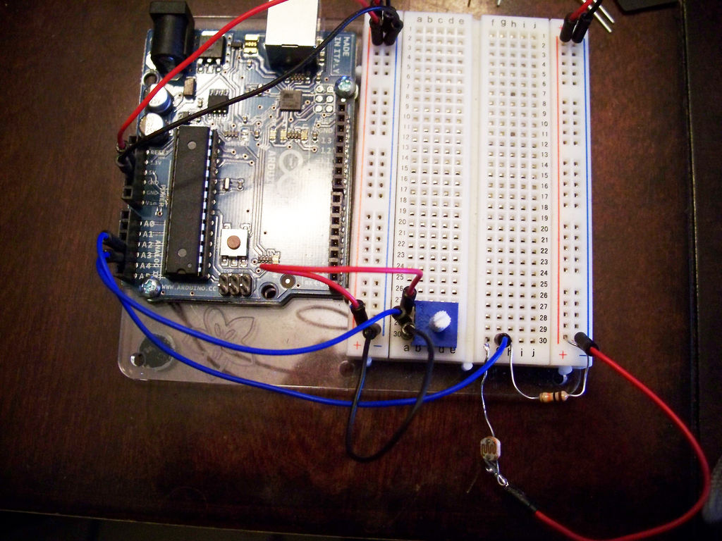
Step 2: Assemble Trigger Circuit
– Photoresistor – Senses when the master flash is triggered
Start by inserting your 10k resistor into the positive rail then into a terminal leaving 2 spaces to the left.
In the first space we will connect a data line going from analog input 3.
In the farthest left terminal on this strip we will insert one end of the photoresistor with the end returning to the negative rail.
– Potentiometer – To adjust threshold of light that will trigger relay
Place your pot into the board.
Connect pin 1 to your positive rail.
Pin 2 will be a data line that goes to analog input 4.
Connect pin 3 of the pot to your negative rail.
– Push button – To manually trip the slave flashes
Insert the push button into the board.
Insert the anode or positive end of one of the red LED’s (the longer leg) into the positive rail and the cathode inline with your button.
On the other end of the button connect a data line going to analog input 1.
After the data line we need to connect a wire to the negative rail.
Step 3: Assemble Relay Circuit
– Transistor – Used to trip the relay
Insert your transistor into the board.
First we will connect the emitter to the negative rail.
Next we will connect our 2.2k resistor to the base and then to digital pin 2.
Finally we are going to connect the collector to the negative of our relays coil (for now just connect a wire to the collector and leave the other end unplugged.
– Relay – Used to fire the slave flashes.
Insert the relay into the board over the gap.
Just above the relay insert the diode with the silver band to the right.
Now take a wire and connect the diode to the coil on both sides (yellow wires in the picture)
Next take the wire we left unplugged from the collector of the transistor and plug it in in-front of the yellow wire going to the diode.
On the positive side of the relays coil (right side) in-front of the diode we are also going to connect to our positive rail.
Next connect a wire to the common on each side of your relay (blue wires pictured) and a wire on each of the normally open contacts of the relay (white wires pictured). This is where our flash will connect to later
Step 4: Assemble Display Light Circuit
Finally, we will assemble the circuit that controls the display lights.
– Red LED – Busy light
Insert the red LED into the board.
Connect the cathode to digital pin 8.
Connect the anode to the positive rail.
– Green LED – Ready light
Insert the red LED into the board.
Connect the cathode to digital pin 7.
Connect the anode to the positive rail.
For more detail: Arduino Flash Controller for Photography