Summary of Using the Sparkfun Motor Driver 1A Dual TB6612FNG using Arduino
This guide walks a beginner through using SparkFun’s Motor Driver 1A Dual TB6612FNG with an Arduino to build a two‑motor differential-drive robot. It covers parts, soldering headers and battery leads, breadboard layout, wiring power and control pins, connecting motors and separate motor supply, and basic motor behaviors (forward, reverse, turning). Emphasis is on practical setup details, common pitfalls, and keeping motor and logic power grounds common.
Parts used in the Sparkfun Motor Driver 1A Dual TB6612FNG Project:
- Sparkfun Motor Driver 1A Dual TB6612FNG
- Header pins (2 sets of 8)
- Breadboard
- Connecting wires / jumper wires
- 1N4001 rectifier diodes (8)
- Arduino Uno R3
- 6V power supply (4x 1.2V NiMH battery holder used)
- 9V battery with 2.1mm barrel connector
- 2 DC motors (Pololu 250:1 micro metal gearmotor used)
- Mounting brackets and wheels (Pololu extended gearmotor brackets and 32x7 wheels used)
- Body construction materials (Meccano, Lego, corrugated card, etc)
- Soldering iron
- Resin core solder
- Wire strippers
As a beginner myself, I struggled to find a one-stop set of instructions to get up and running with Sparkfun’s Motor Driver 1A Dual TB6612FNG. This motor driver breakout board is exceptional value, is beautifully small, but does need a little more effort to get it working.
The TB6612FNG is an H-Bridge driver – I won’t go into the technicalities of how it works, but the end result is that it can turn a connected motor in either direction and at a variable speed. This allows you to build a very agile robot driven by 2 motors that can:
– move forward
– move backward
– turn in a very tight circle by driving one motor forward and one motor in reverse
– a variety of other moves using differential motor speeds and directions
To keep this instructable focused on the driver, I’ve built the bot on a simple Meccano body and haven’t extended it to include any obstacle detection – the bot just drives a set pattern.
Before you start – the driver’s specs:
– Logic supply voltage (VCC) of 2.7-5.5 VDC
– Motor supply voltage (VM) up tp 15VDC
– Current of 1.2A constant per channel (3.2A peak)
– Drives up to 2 motors
Images:
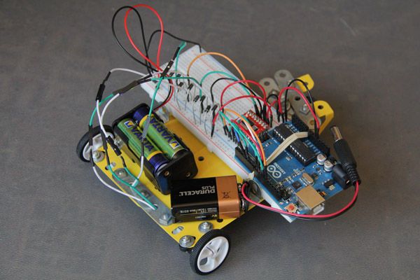
1. Finished Robot
2. The TB6612FNG breakout board
3. Full circuit diagram
Step 1: Get your stuff
First: The Ingredients
– 1 x Sparkfun Motor Driver 1A Dual TB6612FNG
– 1 x set of Header pins
– 1 x Breadboard plus connecting wires
– 8 x 1N4001 rectifier diodes (or similar)
– 1 x Arduino Uno R3
– 1 x 6V power supply (I used 4x 1.2V NiMH rechargeables in a holder)
– 1 x 9V battery with a 2.1mm barrel connector
– 2 x DC motors not exceeding the driver’s current and voltage rating (I used Pololu’s 250:1 micro metal gearmotor for their manageable RPM and high torque)
– Mounting brackets and wheels (I used Pololu’s extended gearmotor brackets and 32×7 wheels – small wheels = manageable speed)
– Something to build the body (Meccano, Lego, thick corrugated card, etc)
Second: The Cooking Utensils
– Soldering Iron
– Resin core solder
– Wire strippers
Step 2: Solder Your Connections
You’ll need to solder a few connections before you get started. I found the fine solder work to be daunting, but randofo’s How-To helped immensely – along with a good dose of practice on some old boards I found lying around.
The breakout board
The TB6612FNG breakout comes without pins – so you’ll need to solder your own.
Snap 2 sets of 8 header pins off the strip using pliers to get a clean break on the right pin. Place the header pins into a breadboard, and then the breakout board on top of this – this will ensure the right spacing and a 90 degree angle between the board and the header pins. I’ve also used play-doh to hold pins in place (play-doh won’t melt, it simply goes crisp and can be picked off). You’ll see from my less-than-fine solder work that I’m still getting to grips with my soldering iron!
Battery connections – the Motor’s battery
The motor will run off a separate 6V source. Depending on the type of connector you have for your battery holder, you may need to solder header pins onto the leads – the power for the motor will connect into the breadboard. (The breakout board has capacitors on-board to isolate noise from the motor, so no need to add these yourself)
Battery connections – the Arduino battery
The Arduino will run off a 9V battery, so that it doesn’t need to be tethered to the USB cable. Depending on the connector/holder you have you may need to solder a 2.1mm barrel connector onto the leads (make sure the centre pin is soldered to the positive lead). Alternatively buy a holder with a connector already attached.
Motor Terminals
Finally, solder wires to the motors’ terminals. I used jumper wires, stripped the one end and soldered it onto the motor. That way, you have the pins to connect the motor to the breadboard.
Images:
1. Soldering the breakout board (can you tell I’m still learning!?!)
2. Battery connectors soldered
3. Motor terminals soldered and motors mounted
Step 3: Set Your Breadboard Up
I’ve used a rubber band to hold my Arduino onto my breadboard. This prevents any accidental shorting of contacts on the underside of the Arduino, and keeps it attached to the breadboard – you can’t accidentally de-wire your whole project if the breadboard wanders too far from the Arduino!Position the Motor Driver
Place the TB6612FNG breakout board onto the breadboard. It needs to straddle the break down the middle of the breadboard so as to keep the two rows of pins on separate circuits. The one side of the driver board handles inputs, and the other outputs.
Power Rails
My breadboard has 2 power rails – I use one (the top one in the images) to provide the Arduino/TB6612FNG power, and the other (the bottom one) to provide the Motor’s power. You need to drive the motors from a separate power source as the current the motors draw is likely to be too much for the Arduino to handle. You must connect the GND from the two sources to ensure a common ground.
1. Mounting the breakout board
2. Overall circuit diagram
3. Physical circuit, motors and motor batteries off-frame (note the jumper cable on the left connecting the ground from the two power sources)
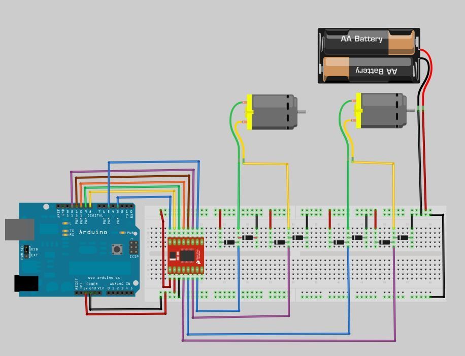
Step 4: Connect the Arduino
Now wire the Breakout board to the Arduino – both the control pins and the power.
Connect the Power:
The power you’re connecting here is the power needed to drive the TB6612FNG, not the power to drive the motors.
– Connect the Arduino 5V to the VCC
– Connect the Arduino GND to the GND
Connect the Control Pins:
Each motor (labelled A and B) has 3 control inputs: IN1 and IN2 to control the direction it turns, and a PWM input to control speed. The STBY pin is used to bring the motors to life / put them to sleep
– Pin 3 —> PWMA
– Pin 8 —> AIN2
– Pin 9 —> AIN1
– Pin 10 —> STBY
– Pin 11 —> BIN1
– Pin 12 —> BIN2
– Pin 5 —> PWMB
Images:
1. Connect the power
2. Connect the control pins
3. Circuit Diagram
4. Reverse side of the breakout board, showing connection points
Step 5: Connect the Motors
Next is to connect the motors to the breadboard.
Connect Motor Power
Connect the bottom power rail (6V) to the breakout board VM pin
Connect the Output Pins
Connect the A01 & A02 / B01 and B02 pins of the breakout board to the breadboard. These pairs (01 and 02) will drive each motor – the TB6612FNG will switch the polarity and control the voltage of these to determine the direction and the speed that the motor spins in.
In the next step we’ll connect the motors to the breadboard (with some back EMF protection)
Images:
1. Connect the power from the bottom rail
2. Connect the outputs to the breadboard, ready to accept the motor connections. Note motor battery connected in bottom left
Soldering Iron
Resin core solder
Wire strippers
Motor terminals
For more detail: Sparkfun Motor Driver 1A Dual TB6612FNG using Arduino
- What voltages does the TB6612FNG require?
The logic supply VCC is 2.7 to 5.5 VDC and the motor supply VM is up to 15 VDC. - How much current can each channel handle?
The driver supports 1.2 A constant per channel and 3.2 A peak. - Do I need separate power supplies for the Arduino and motors?
Yes, the motors are driven from a separate motor power source and the Arduino runs from its own 9V supply; you must tie the grounds together. - Which Arduino pins are used for motor A controls?
Pin 3 to PWMA, Pin 8 to AIN2, Pin 9 to AIN1, and Pin 10 to STBY (shared control). - Which Arduino pins are used for motor B controls?
Pin 11 to BIN1, Pin 12 to BIN2, and Pin 5 to PWMB. - How should the TB6612FNG breakout be placed on the breadboard?
Place it straddling the center break so the two rows of pins sit on separate circuits (inputs one side, outputs the other). - Do I need to add capacitors for motor noise?
No, the breakout board has on-board capacitors to isolate motor noise. - How are motors connected to the TB6612FNG outputs?
Connect each motor to its corresponding output pair A01/A02 or B01/B02 on the breakout board. - What should I solder before assembling?
Solder the header pins to the breakout, solder battery connectors if needed, and solder wires to the motor terminals. - Can the TB6612FNG drive two motors simultaneously?
Yes, it drives up to two motors (each on its own channel).