Summary of Using The PCF8575 i2c i/o Expander To Read Inputs With Arduino
This article demonstrates adding hundreds of extra inputs to an Arduino using the PCF8575 i2c expander chip and only two wires. It covers circuit assembly with breakout boards, resistors, and buttons, explains the i2c communication protocol via the Wire library, and provides code examples for reading data while noting version-specific syntax changes in Arduino 1.0.
Parts used in the Arduino i2c Input Expansion Project:
- PCF8575
- SMD to DIP breakout board
- Teensy-Arduino or any Arduino
- 3x pushbutton
- 3x resistors
- 3x LED
This Instructable will show you just how easy it is to add extra inputs to your Arduino. You can use this technique to add hundreds of extra inputs to your Arduino with only two wires by using a fancy communication protocol called i2c (eye-squared-see).
What I have used…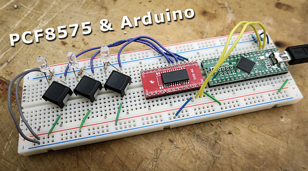
- PCF8575
- SMD to DIP breakout board
- Teensy-Arduino (any Arduino will work)
- (3x) pushbutton
- (3x) resistors
- (3x) LED
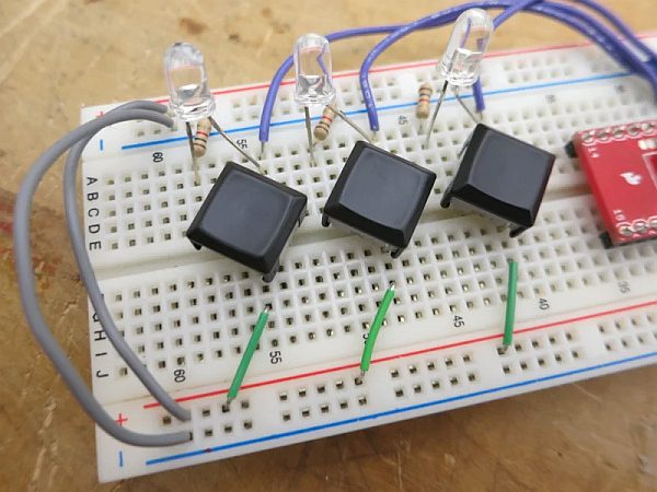
Step 1: Build the Circuit
The SDA and SCL lines enable i2c communication.
Which pins are SDA and SCL?
Uno, Ethernet: A4 (SDA), A5 (SCL)
Mega2560: 20 (SDA), 21 (SCL)
Leonardo: 2 (SDA), 3 (SCL)
Due: 20 (SDA), 21 (SCL), SDA1, SCL1
The PCF8575 is not available in a breadboard-friendly form (only surface mount). The handy Sparkfun breakout boards allow you to plug this chip into the breadboard for prototyping.
You need to connect a 10kOhm resistor between SDA/SCL and PWR (see image).
Also note that push-buttons need resistors. If you want an i2c i/o expander in which you don’t need resistors on the switches check out the MCP23017.
If you are having troubles hooking up your switches try this for reference.
I included the LEDs only to provide some feedback. They add no functionality.
Step 2: The Code
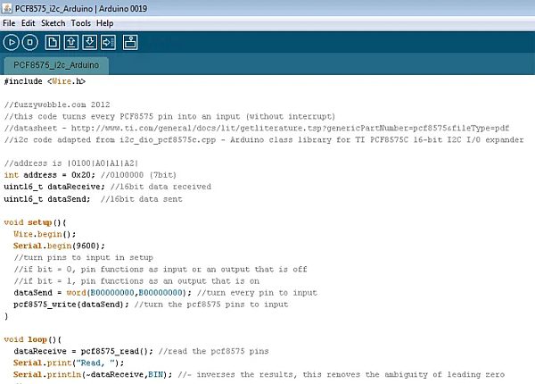
Okay now the scary part – the code.
If you want to use i2c devices it is best to understand how the code works otherwise you are going to have many problems down the road.
i2c is handled using the Arduino wire library.
To understand i2c you are going to have to do a bit of reading. Expect to be very confused at first. If you plan to do any intermediate and advanced electronics learning i2c is imperative.
I will try to give a very simple explanation of i2c.
One thing you will notice, as you begin to work with electronics, is that you always have a mess of wires. A long time ago Phillips said ‘hell with all these wires – we need a way for all the devices to talk to eachother with only two wires’. Shortly after, i2c was created. Now you can buy i2c chips which do just about everything, and all these chips are able to communicate with eachother using only two wires. i2c is often called the ‘two wire interface’.
So how do these devices talk to each other? Well, they all have an address, much like you have a mailing address at your house. With this unique address you can talk to each device individually. The Arduino, which would be the master-i2c-device, can send instructions to the individual slave-i2c-devices using a fancy communication protocol. In Arduino, the send-communication looks like this:
Wire.send(someDate); //what data are you sending this device
Wire.endTransmission(); //end communication
if(Wire.available()){
The Arduino code file is attached below.
NOTE if you are using Arduino1.0
Wire.send and Wire.receive statements MUST BE changed to Wire.write and Wire.read
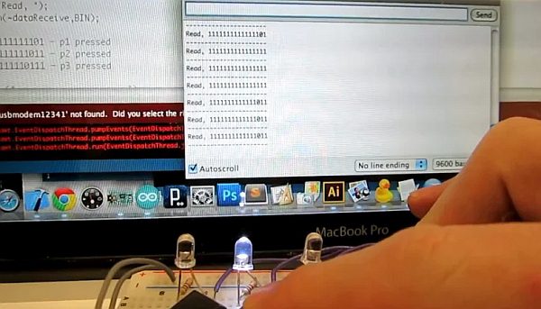
Step 3: Testing
Source: Using The PCF8575 i2c i/o Expander To Read Inputs With Arduino
- How many wires are needed to add extra inputs using this technique?
You can add hundreds of extra inputs using only two wires. - What pins are SDA and SCL on an Uno?
The SDA pin is A4 and the SCL pin is A5. - Can I use a standard breadboard with the PCF8575 chip directly?
No, the PCF8575 is only available in surface mount form, so you need a breakout board. - What resistance value resistor should be connected between SDA/SCL and PWR?
You need to connect a 10kOhm resistor between SDA/SCL and PWR. - Which Arduino library handles i2c devices?
i2c is handled using the Arduino wire library. - Does the project include LEDs for functionality?
The LEDs were included only to provide feedback and add no functionality. - What change is required if using Arduino 1.0?
Wire.send and Wire.receive statements MUST BE changed to Wire.write and Wire.read. - Is there an alternative chip that does not require resistors on switches?
Yes, you can check out the MCP23017 if you want an i2c i/o expander without resistors on the switches.