
Summary of Using Arduino and Pd for musical live performance
This article details a custom Arduino-to-Pd communication system for musical performances, replacing standard Firmata to optimize data transmission. The author implemented a specific byte-based protocol to minimize USB traffic, enabling features like built-in pull-up resistors, local calculations, and change-only messaging. This approach supports various input devices, including foot switches, glove-mounted sensors, and forearm keypads, while utilizing a C external on the Pd side for efficient parsing instead of CPU-intensive bit-shifting methods.
Parts used in the Arduino-Pd Musical Interface:
- Arduino Duemilanove microcontroller
- Firmata software (mentioned as an alternative)
- Pduino library (mentioned as a comparison)
- Custom C external for message parsing
- Three foot switches in a box
- Three push buttons mounted on a glove
- Force-sensitive resistor mounted on a glove
- 12-button keypad with resistor matrix
Connecting an Arduino microcontroller to Pd is no big problem: You can just put Firmata on your Arduino and use the Pduino library for communication on the Pd side.
But sometimes Firmata is not the answer to every problem: You may want to turn on the built-in pull-up resistors for digital input pins, you may want to do some calculation on the Arduino before sending a message, or you may want to send a message from Arduino to Pd only on change.
In fact, I wanted to do all of the above, but not use Arduino for output. This led to the following electronics and code.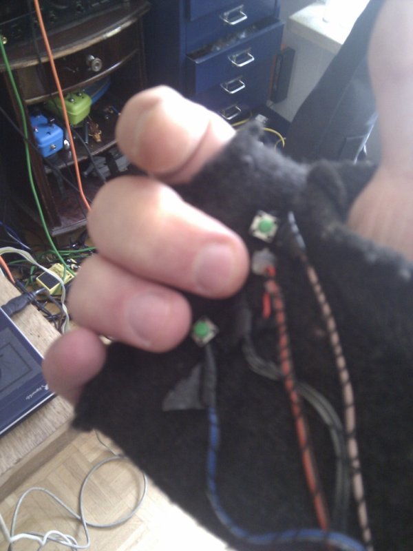
Connecting Inputs to Arduino
I have connected several push buttons to the Arduino, and one variable resistor. All push buttons are open an close on push. All connected devices:
- Three foot switches in a box.
- Three push buttons and a force-sensitive resistor mounted on a glove, worn on the right hand.
- A keypad consisting of 12 push buttons with a resistor matrix similar to this setup (in German). The main difference in my setup is the usage of values ten times as in the example, as the thin cables have a non-negligable resistance. This is mounted on my left forearm
Message Passing between Arduino And Pd
I wanted to minimize the data sent from Arduino over USB to the host computer. I came up with the following “protocol”, that uses 1 byte for a digital value and 2 bytes for analog values.
- Digital message
100ppppv- Analog message
11pppvvv 0vvvvvvv
p denotes bits used for encoding the pin number, v bits used for values.
As the Arduino Duemilanove – the one that I use – has 14 digital pins, 4 bits (0-15) are necessary to encode the values, 6 analog ins can be encoded in 3 bits (0-7). Digital pins only read 0 or 1, so only one bit is needed for encoding the value, analog pins read values 0-1023, which corresponds to 10 bits.
If a byte starts with a value of 11, then this byte and the following one starting with 0 together are an analog message. If a byte starts with 100, then the message is a digital message.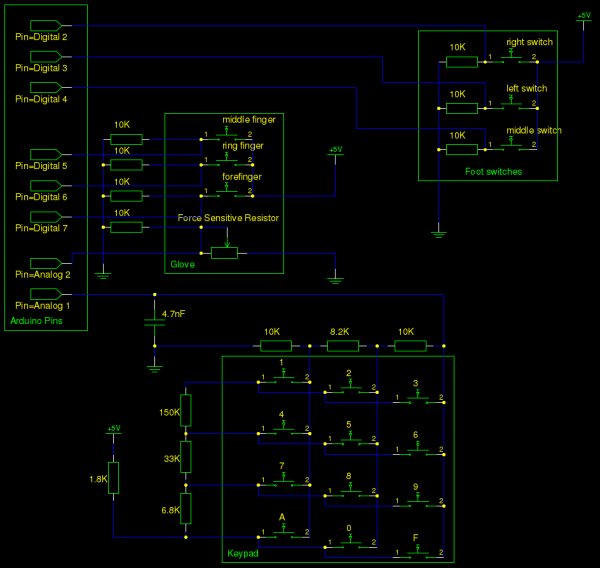
On Pd’s side, messages are parsed and then output in the same way as [pduino] does it: (a|d) [pin number] [value]. That design allows you use it as a drop in replacement.
I first tried to parse messages with bit shifting and [expr], but that was too CPU intensitive, so I have created my own external in C. That external does the bit shifting and then outputs messages as lists.
Pd Patch
I am using the setup mostly for live performances, and the demo patch included in the source code is the actual patch that I use. It also makes heavy use of my abstractions.
A demo video will follow soon.
For more detail: Using Arduino and Pd for musical live performance
- Why did the author choose not to use Firmata?
The author needed to turn on built-in pull-up resistors, perform calculations on the Arduino before sending messages, and send messages only when values change. - What input devices were connected to the Arduino?
The setup included three foot switches, three push buttons with a force-sensitive resistor on a glove, and a 12-button keypad on the left forearm. - How does the custom protocol encode digital messages?
Digital messages start with a byte value of 100, using one bit for the value since digital pins only read 0 or 1. - How does the custom protocol encode analog messages?
Analog messages start with a byte value of 11, followed by another byte starting with 0, utilizing 10 bits to represent values from 0 to 1023. - Why was a C external created for the Pd side?
Initial attempts using bit shifting and [expr] were too CPU intensive, so a custom C external was developed to handle the parsing efficiently. - What is the structure of the output messages on Pd?
Messages are parsed and output as lists in the format (a|d) pin number value, allowing it to function as a drop-in replacement for pduino. - How many bits are required to encode the pin numbers for digital inputs?
Four bits are necessary to encode the 14 digital pins available on the Arduino Duemilanove. - How many bits are required to encode the pin numbers for analog inputs?
Three bits are sufficient to encode the 6 analog inputs available on the Arduino Duemilanove.
