Summary of Understanding Logic Analyzer basics using SCANALOGIC-2 EDU KIT
A logic analyzer captures and displays digital signal timing, ideal for debugging bus violations. Unlike oscilloscopes measuring analog details, it samples logic states across many channels. This article uses the SCANALOGIC-2 kit to demonstrate features like protocol decoding and two modes: timing (asynchronous) and state (synchronous).
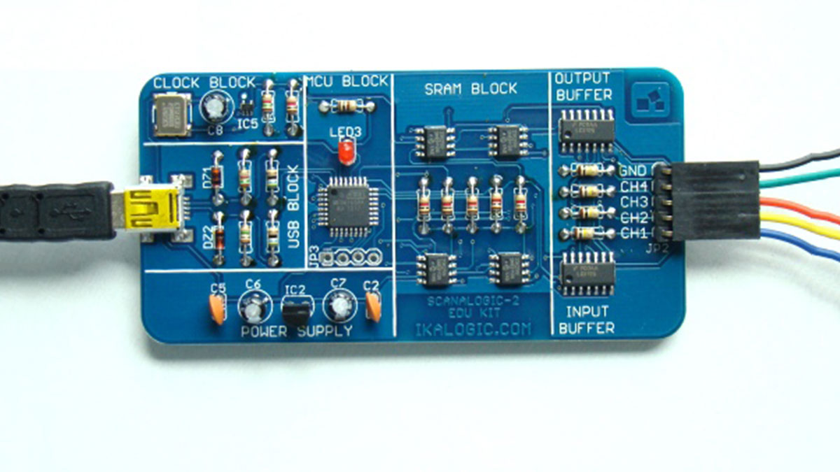
Parts used in the SCANALOGIC-2 Educational Kit:
- Atmega168 microcontroller
- Memory chips
- I/O buffer chips
- Quartz oscillator
- Resistors
- Capacitors
- Regulator IC
- Diodes
- Gripper probes
A logic analyzer is an excellent tool for capturing many digital signals at once and displaying their timing relationships. It is particularly useful in verifying and debugging digital circuits. This tutorial is intended to provide a quick overview of a logic analyzer tool and its uses in analyzing and decoding data flowing on multiple signal lines or bus in a digital system. The logic analyzer tool is extremely helpful in troubleshooting problems arising from timing violations and transients on buses. In this article, I am going to use the SCANALOGIC-2 educational kit from IKALOGIC to illustrate very basic features of a logic analyzer.
Logic analyzer vs oscilloscope
Several types of electronic measurement tools are used to test and verify digital circuits. A digital oscilloscope is one of the most commonly used tools in an electronics lab. The oscilloscope is used for general-purpose signal viewing and it allows to make accurate measurements of various attributes of the signal such as rise- and fall-times, peak amplitude, frequency, the elapsed time between edges, etc. Typical digital oscilloscopes have up to four signal inputs, which means you can simultaneously observe four signals and their attributes. However, the oscilloscope cannot help you when you need to measure digital signals on a 32-bit microcprocessor bus simultaneously because it doesn’t have that many channels. A logic analyzer tool can serve this purpose. Although it grew out of an oscilloscope, the logic analyzer have different capabilities, and it measures and analyzes signals differently than an oscilloscope. Instead of measuring analog details, the logic analyzer only detects the logic state of a signal. Logic analyzers can have over 100 channels (some sophisticated ones have over thousand channels). Because they can capture and display logic states of many signal lines at once, logic analyzers are very helpful for verifying time relationship between the signals. They can also decode information sent over the microprocessor bus and present them in a meaningful form.
Logic analyzers present data basically in the same way as oscilloscopes do with time axis along horizontal. But the vertical axis of logic analyzer has only 1-bit resolution required to indicate either a logic High or a logic Low. When you connect a logic analyzer to a digital circuit, you’re only concerned with the logic state of the signal, and not analog details as oscilloscopes do. Besides, logic analyzers can’t display data in real time. They first capture the signals and display them later. They are very useful when looking at time relationship between many signals at one glance. It can also decode information sent over the microprocessor buses and present them in a meaningful form.
The basic defining characteristics of a logic analyzer are the number of input channels it can sample, the maximum sampling rate, and the memory depth for storing the samples. The specification of memory depth defines how many captured samples can be stored per channel in a single run. For example, an analyzer with 32K depth can store 32K samples per channel. If you use a sampling frequency of 1 million samples per second, then it will fill up just in 32 milliseconds. Larger memory depths allow you to sample data for longer time, which is helpful to spot and correct a timing violation on bus.
Modes
Logic analyzers have two basic modes of operation: timing mode and state mode.
In timing mode, the data is sampled at regular intervals according to a clock internal to the logic analyzer. As such there is no fixed timing relationship between a target system and the samples acquired by the logic analyzer. The samples are stored in the memory and are used later to analyze the timing relationship between the signals. This mode of operation is also known as asynchronous acquisition and is useful in debugging mostly hardware problems.
The timing relationship between the signals is not particularly useful while tracking down software related problems. The software developer is more interested to see the instruction flow of the program. In state mode, a signal from the target device (usually a microprocessor clock) defines the sample point. Signals are captured on the active edge of every clock signal received from the target device. In this case, the relative timing information between the signals is unimportant. Since the data are sampled during the active edge of the system clock, the logic signals are stable and represent a valid state of the target system. Therefore, with multiple samples, it is possible to capture and display successive states of the system in a sequence. This points up the major difference between timing and state mode. The timing analyzer has an internal clock to control sampling, so it asynchronously samples the system under test. A state analyzer synchronously samples the system since it gets its sampling clock from the system.
Triggering
A logic analyzer needs a trigger signal that basically tells it when to start recording samples. Since a logic analyzer has a limited amount of memory for storing samples, a trigger helps to capture the action of interest properly. A trigger is normally defined by a logic condition built on the sampled data that has to be met in order to capture the data. Many conditions can be used to trigger a logic analyzer. For example, a change in the logic state of a single line can be used as a trigger. Similarly, in a more complex system, recognizing a specific binary value on a bus or a sequence of pre-defined data values can be used as triggers. Although there is no theoretical limit on how you would define a trigger, complex trigger algorithms are difficult to implement because the trigger event has to be evaluated in real time.
SCANALOGIC-2
SCANALOGIC-2 is an educational kit that allows you to build a low-cost four channel logic analyzer at home. It is based on ATMEL’s Atmega168 microcontroller. It connects to a PC through USB port and uses a free PC software called ScanaStudio to visualize and analyze the captured signals. The key features of SCANALOGIC-2 are:
- Sampling rate: 20 Million samples per seconds
- No. of channels: 4
- Memory depth: 256K per channel (total 1 MByte)
- Protocol decoding: I2C, SPI, UART, 1-Wire
- Digital output capability: PWM, FM, UART packets
When you order the Scanalogic-2 EDU KIT, the board comes with presoldered SMT components that include the microcontroller, memory chips, I/O buffer chips and quartz oscillator. Rest of the through-hole components (resistors, capacitors, regulator IC, and diodes) are to be soldered by yourself, which is pretty easy. The KIT also includes gripper probes to hook the logic analyzer to your circuit.
- What is the primary function of a logic analyzer?
To capture many digital signals at once and display their timing relationships. - How does a logic analyzer differ from an oscilloscope?
A logic analyzer detects logic states only, while an oscilloscope measures analog attributes like rise-time and amplitude. - Can a logic analyzer display data in real time?
No, it must first capture signals and then display them later. - What are the two basic modes of operation for logic analyzers?
Timing mode and state mode. - How does timing mode sample data?
It samples at regular intervals using an internal clock without a fixed relationship to the target system. - How does state mode determine when to sample?
It synchronously samples on the active edge of a clock signal received from the target device. - Why is a trigger signal necessary?
It tells the analyzer when to start recording to ensure the action of interest is captured within limited memory. - What sampling rate does the SCANALOGIC-2 support?
20 Million samples per second. - Which protocols can the SCANALOGIC-2 decode?
I2C, SPI, UART, and 1-Wire. - How does the SCANALOGIC-2 connect to a computer?
It connects via a USB port.