Introduction
Isolated DC/DC converters are required in a broad range of applications including power metering, industrial programmable logic controllers (PLCs), insulated-gate bipolar transistor (IGBT) driver power supplies, industrial fieldbus, and industrial automation. These converters often are used to provide galvanic isolation, improve safety, and enhance noise immunity. Moreover, they can be used to generate multiple output voltage rails including dual-polarity rails.
In terms of output voltage regulation accuracy, isolated DC/DC converters usually fall into three categories: regulated, unregulated, and semi-regulated. This article discusses various regulating schemes and the corresponding topologies. Factors affecting regulation accuracy are examined in detail. This leads to some design tips to improve regulation accuracy in practical designs. Additionally, the pros and cons of each scheme are presented to provide a guideline for choosing an appropriate solution for a specific application need.
Feedback and control of isolated DC/DC converters
Isolated DC/DC converters typically use a transformer to electrically isolate the output from the input of the power stage.
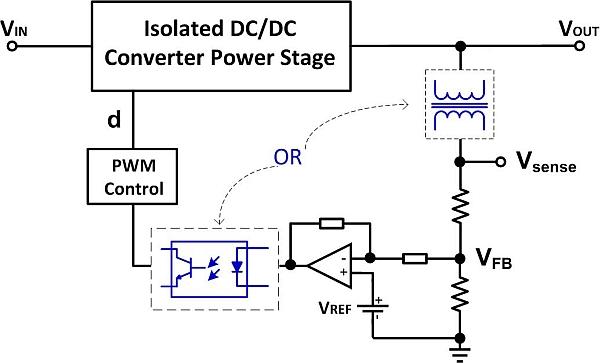
In a closed-loop isolated DC/DC converter (Figure 2), the feedback circuitry senses the output voltage and generates an error by comparing the sensed voltage with its target (feedback voltage reference). The error is then used to adjust the control variable (duty cycle in this example) to compensate the output deviation. Galvanic isolation between control circuitry on primary side and secondary side is also essential. Such isolation can be achieved by utilizing either a transformer or an optocoupler. Assuming the reference voltage VREF is precise and stable over temperature, regulation accuracy mainly depends on output voltage sensing accuracy (in other words, how well VSENSE resembles VOUT).
For more detail: Understanding isolated DC/DC converter voltage regulation

