Summary of TV-B-Gone Kit Using Arduino
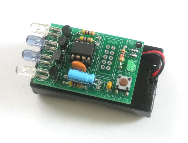
The TV-B-Gone kit is a DIY project allowing users to build a universal remote that turns off TVs using infrared signals. Developed with inventor Mitch Altman, this high-power version includes four IR LEDs for ranges exceeding 100 feet and teaches soldering skills. It covers 46 common codes for North American and Asian televisions but does not work on LED signs or computer monitors without remote ports.
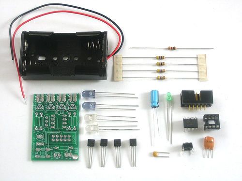
Parts used in the TV-B-Gone Kit:
- Microcontroller (ATTINY85V-10-PU)
- 8-pin socket
- 8.00 MHz ceramic oscillator
- 100uF/10V capacitor
- Ceramic 0.1uF capacitor
- 47 ohm resistors (Qty 4)
- 1.0Kohm resistor
- Narrow beam IR LEDs (Qty 2)
- Wide beam IR LEDs (Qty 2)
- 3mm LED
- 6mm tact switch button
- NPN Transistors (Qty 4)
- 10 pin box header
- 2 x AA battery holder
- Circuit board
Tired of all those LCD TVs everywhere?
Want a break from advertisements while you’re trying to eat?
Want to zap screens from across the street?
The TV-B-Gone kit is what you need! This ultra-high-power version of the popular TV-B-Gone is fun to make and even more fun to use.
Built in co-operation with Mitch Altman (the inventor of the TV-B-Gone – http://www.tvbgone.com) this kit is a great way to build something truly useful!
Step 1: F.A.Q.
What is a TV-B-Gone Kit?
TV-B-Gone http://www.tvbgone.com/ is a ‘universal’ remote control device, it is basically like a remote control but with only the “Power” button. This is a kit version of that product.
How are the kit and original TV-B-Gone product related?
Mitch Altman http://www.pbs.org/mediashift/2006/04/digging_deepertvbgone_device_s.html (inventor of the TV-B-Gone) and his company Cornfield Electronics http://www.cornfieldelectronics.com/ worked together with me (Adafruit Industries) to develop a kit version of the TV-B-Gone. Mitch thinks open source kits are awesome!
Why should I get a kit if I can just buy a TV-B-Gone ready made?
This kit is for learning how to solder and maybe even a little of how remote controls are designed. The kit version also has 2 AA batteries and 4 high power output IR LEDs to allow for much longer distances than the keychain product, more than 100 ft! It’s also easier to hack and adapt for other projects. However, the kit has fewer codes (so there may find a TV once in a while that doesn’t respond), is larger and heavier and requires you to put it together.
I suggest you get one of each!
Does this kit work on all TVs?
We picked the 46 most common codes for North American/Asian TV’s to program into the kit. However, we couldn’t include every code. Field testing has shown that nearly every TV we encountered would turn off, even the most recent LCD and Plasma flat screen TVs!
Note that this kit will not work with LED signs, computer monitors (that are not also televisions) and display signs that don’t have a remote-control port.
What do you mean N. America/Asia? Does this kit work with European TVs?
A large number of newer European TVs will work with TV-B-Gone kit, but its not as likely. For example, instead of 90% success, its more like 50%
How close do I have to be for the TV-B-Gone kit to work?
The closer the better, but we’ve found that if you have pretty good aim, you can be 100′ (30m) or farther.
I’m not able to turn off the TV from more than 30 feet away, what’s wrong?
First, perform the test to make sure all 4 IR LEDs are firing.
Second, make sure you have fresh Alkaline batteries installed
Third, try to aim as best as you can at the IR receiver, usually a small dark plastic plate on the front of the TV
Finally, try many different TVs. Some TVs simply do not respond as well from far away as others.
I want more range! How can I make the kit more powerful?
Make sure you have fresh Alkaline batteries. They work better than rechargeable.
You can swap out the 2 AA battery holder for a 3 AA battery holder. This will give even better performance! Using C or D cell batteries will give longer run time but won’t increase the power.
Do not use 9V batteries or more than 3 1.5V alkaline batteries, you can permanently damage the kit!
Step 2: Preparation
Don’t forget to learn how to use your multimeter too!
http://www.ladyada.net/learn/multimeter/index.html
Tools
There are a few tools that are required for assembly. None of these tools are included. If you don’t have them, now would be a good time to borrow or purchase them. They are very very handy whenever assembling/fixing/modifying electronic devices! I provide links to buy them, but of course, you should get them wherever is most convenient/inexpensive. Many of these parts are available in a place like Radio Shack or other (higher quality) DIY electronics stores.
I recommend a “basic” electronics tool set for this kit, which I describe here.
http://www.ladyada.net/library/equipt/kits.html#basic
Soldering iron. One with temperature control and a stand is best. A conical or small ‘screwdriver’ tip is good, almost all irons come with one of these.
A low quality (ahem, $10 model from radioshack) iron may cause more problems than its worth!
Do not use a “ColdHeat” soldering iron, they are not suitable for delicate electronics work and can damage the kit (see here) http://www.epemag.wimborne.co.uk/cold-soldering2.htm
Solder. Rosin core, 60/40. Good solder is a good thing. Bad solder leads to bridging and cold solder joints which can be tough to find. Don’t buy a tiny amount, you’ll run out when you least expect it. A half pound spool is a minimum.
Multimeter/Oscilloscope. A meter is helpful to check voltages and continuity.
Flush/diagonal cutters. Essential for cutting leads close to the PCB.
Desoldering tool. If you are prone to incorrectly soldering parts.
‘Handy Hands’ with Magnifying Glass. Not absolutely necessary but will make things go much much faster.
Check out my recommendations and where to buy.
http://www.ladyada.net/library/equipt/kits.html#basic
Good light. More important than you think.
Step 3: Parts
Check to make sure your kit comes with the following parts. Sometimes we make mistakes so double check everything and email [email protected] if you need replacements!
Name : IC1
Description : Microcontroller (preprogrammed when purchased in a kit)
Part # : ATTINY85V-10-PU http://www.atmel.com/dyn/resources/prod_documents/doc2586.pdf
Distributor : Mouser, Digikey (unprogrammed, of course)
Qty : 1
http://www.mouser.com/search/ProductDetail.aspx?R=ATTINY85V-10PUvirtualkey55650000virtualkey556-ATTINY85V10PU
http://search.digikey.com/scripts/DkSearch/dksus.dll?Detail?name=ATTINY85V-10PU-ND
Name : IC1′
Description : 8-pin socket
Part # : Generic
Distributor : Mouser, Digikey
Qty : 1
http://www.mouser.com/search/ProductDetail.aspx?R=1-390261-2virtualkey57100000virtualkey571-1-390261-2
http://search.digikey.com/scripts/DkSearch/dksus.dll?Detail?name=3M5473-ND
Name : XTL1
Description : 8.00 MHz ceramic oscillator. It might also be blue.
Part # : ZTT-8.00MT or equivalient http://www.ecsxtal.com/store/pdf/ZTT.pdf
Distributor : Digikey, Mouser
Qty : 1
http://search.digikey.com/scripts/DkSearch/dksus.dll?Detail?name=X905-ND
http://www.mouser.com/search/ProductDetail.aspx?R=ZTT-8.00MTvirtualkey59070000virtualkey520-ZTT800MT
Name : C2
Description : 100uF/10V capacitor
Part # : Generic
Distributor : Digikey, Mouser
Qty : 1
http://www.digikey.com/scripts/DkSearch/dksus.dll?Detail?name=P963-ND
http://www.mouser.com/search/ProductDetail.aspx?R=140-XRL10V100-RCvirtualkey21980000virtualkey140-XRL10V100-RC
Name : C1
Description : Ceramic 0.1uF capacitor (104)
Part # : Generic
Distributor : Digikey, Mouser
Qty : 1
http://www.digikey.com/scripts/DkSearch/dksus.dll?Detail?name=BC1160CT-ND
http://www.mouser.com/search/ProductDetail.aspx?R=C410C104K5R5TA7200virtualkey64600000virtualkey80-C410C104K5R-TR
Name : R1-R4
Description : 47 ohm 1/4W 5% resistor (yellow violet black gold)
Part # : Generic
Distributor :
Qty : 4
Name : R5
Description : 1.0Kohm 1/4W 5% resistor (brown black red gold)
Part # : Generic
Distributor :
Qty : 1
Name : LED2, LED3
Description : Narrow beam IR LED. These have a blue-ish tint.
Part # : Everlight IR333-A http://www.mouser.com/search/ProductDetail.aspx?R=EL-IR333-Avirtualkey63810000virtualkey638-IR333-A
Distributor : Mouser
Qty : 2
http://www.mouser.com/search/ProductDetail.aspx?R=EL-IR333-Avirtualkey63810000virtualkey638-IR333-A
Name : LED1, LED4
Description : Wide beam IR LED
Part # : Everlight IR333C/H0/L10 http://www.everlight.com/pdf/IR333C-H0-L10.pdf
Distributor : Mouser
Qty : 2
http://www.mouser.com/search/ProductDetail.aspx?R=IR333C%2fH0%2fL10virtualkey63810000virtualkey638-IR333C%2fH0%2fL10
Name : LED5
Description : 3mm LED
Part # : Generic
Distributor : Digikey, Mouser
Qty : 1
http://www.digikey.com/scripts/DkSearch/dksus.dll?Detail?name=160-1710-ND
http://www.mouser.com/search/ProductDetail.aspx?R=LTL-1CHGvirtualkey57820000virtualkey859-LTL-1CHG
Name : SW1
Description : 6mm tact switch button
Part # : Omron B3F-1000 (or equiv) http://oeiwcsnts1.omron.com/ocb_pdfcatal.nsf/PDFLookupByUniqueID/E295D1F4221B13C186256FC70058AC0A/$File/D22B3F0305.pdf?OpenElement
Distributor : Digikey, Mouser
Qty : 1
http://www.digikey.com/scripts/DkSearch/dksus.dll?Detail?name=SW400-ND
http://www.mouser.com/search/ProductDetail.aspx?R=B3F-1000virtualkey65300000virtualkey653-B3F-1000
Name : Q1 Q2 Q3 Q4
Description : NPN Transistor (TO-92) that is pin compatible with 2N3904
Part # : PN2222 http://www.fairchildsemi.com/ds/PN%2FPN2222.pdf
Distributor : Mouser, Digikey
Qty : 4
http://www.mouser.com/Search/ProductDetail.aspx?qs=UMEuL5FsraBJOIjLOc%2ftCA%3d%3d
http://search.digikey.com/scripts/DkSearch/dksus.dll?Detail?name=PN2222AFS-ND
Name : JP2
Description : 10 pin box header
Part # :
Distributor : Mouser, Digikey
Qty : 1
http://www.mouser.com/search/ProductDetail.aspx?R=30310-6002HBvirtualkey51750000virtualkey517-30310-6002
http://www.digikey.com/scripts/DkSearch/dksus.dll?Detail?name=HRP10H-ND
Name : BATT
Description : 2 x AA battery holder
Part # : Generic
Distributor : Digikey, Mouser
Qty : 1
http://www.digikey.com/scripts/DkSearch/dksus.dll?Detail?name=2463K-ND
http://www.mouser.com/search/ProductDetail.aspx?R=12BH321A-GRvirtualkey56100000virtualkey12BH321A-GR
Name : PCB
Description : Circuit board
Part # :
Distributor : Adafruit Industries
Qty : 1
http://www.adafruit.com/
v1.1 schematic
If you have a black PCB with v1.1 on it
http://www.ladyada.net/images/tvbgone/tvbgone11.png
Note that the microcontroller must be programmed with the v1.1 firmware.
Any NPN transistor that is pin-compatible with the 3904 should be OK.
Use 940nm IR LEDs.
v1.0 Schematic
If you have a green PCB with v1.0 on it
http://www.ladyada.net/images/tvbgone/schematic.jpg
Note that the microcontroller must be programmed with the firmware.
Any NPN transistor that is pin-compatible with the 3904 should be OK.
Use 940nm IR LEDs.
Step 4: Solder It! part 1
Get Ready…
The first step is to solder the kit together. If you’ve never soldered before, check the Preparation page for tutorials and more.
Go!
Check the kit against the parts list to verify you have all the parts necessary
Put the printed circuit board into a vise or board holder, heat up your soldering iron and make sure you’re ready to go!
The first part we’re going to assemble is the button. The button is a symmetric part so it can go in two ways. Line up the metal legs with the holes in the circuit board and snap it in. The button should sit flat against the circuit board.
Using your soldering iron, heat up a leg of the button and the poke solder into it to make a nice solder joint.
Repeat for all four legs. The solder points should be clean and shiny. See the tutorials for soldering help if you can’t get it right.
http://www.ladyada.net/learn/soldering/index.html
Next is the 1.0 kilo ohm resistor R5. This is the brown-black-red striped part. This resistor sets the brightness of the little indicator LED. Resistors are symmetric, so it can go in either way.
Bend the legs so it looks like a staple and insert it into the R5 location as shown.
Then bend the legs out a bit so that when you turn the PCB over the part doesn’t fall out.
Step 5: Solder It! part 2
solder each leg of the resistor
Use the diagonal cutters to clip off the resistor legs so that only the solder points remain.
Now its time to place the small indicator LED LED5. LED’s are not symmetric and must be placed correctly in order to work. You’ll notice one leg of the LED is longer than the other. This is the positive leg. The positive leg goes into the hole with a + next to it. In the picture shown, its the left hole.
Insert the LED into the correct location, and bend the leads out to keep it from falling out when you turn the PCB over.
Turn the PCB over and solder both leads of the LED.
Clip both leads off the LED.
For more detail: TV-B-Gone Kit Using Arduino
- What is a TV-B-Gone Kit?
It is a kit version of a universal remote control device that functions like a remote with only a Power button. - Does this kit work on all TVs?
No, it programs 46 common codes for North American and Asian TVs and will not work with LED signs or computer monitors lacking remote-control ports. - How close do I have to be for the TV-B-Gone kit to work?
You can be 100 feet or farther away if you have pretty good aim at the IR receiver. - Why should I get a kit if I can just buy a TV-B-Gone ready made?
The kit is designed for learning how to solder and allows for easier hacking and adaptation compared to the keychain product. - I'm not able to turn off the TV from more than 30 feet away, what's wrong?
Check that all 4 IR LEDs are firing, ensure you have fresh Alkaline batteries, aim at the dark plastic plate on the TV, or try different TVs. - How can I make the kit more powerful?
Use fresh Alkaline batteries instead of rechargeables and swap the 2 AA battery holder for a 3 AA battery holder. - Does this kit work with European TVs?
A large number of newer European TVs will work, but success is less likely, estimated around 50% compared to 90% elsewhere. - Can I use 9V batteries for this kit?
No, using 9V batteries or more than 3 1.5V alkaline batteries can permanently damage the kit.