Purpose of the Project: Creating a tunnel book with a light sensor (LDR) and led module using the Pinoo Control Card.
Duration: 2 lessons
Age Group: 7 years and older
Set Used: Pinoo Basic Set
Benefits:
• Learns to code Pinoo control card
• Learns to code the light sensor (LDR).
• Led module learns to code.
• Improves the skill of setting up algorithms.
• Improves coding skill.
Step 1: Desing (Part1)
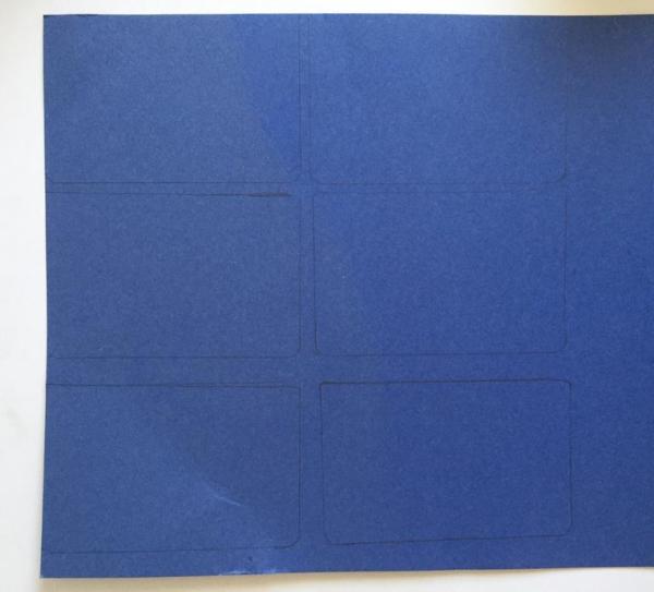
- We draw and cut six rectangles of 21 x13.5 cm on the cardboard.
- We draw a 1 cm wide frame to the rectangles we cut.
- We draw the picture / shapes we want on the area within the frame.
- We paint the picture / shapes we have drawn.
- We cut the areas outside the shape.
Step 2: Desing (Part2)
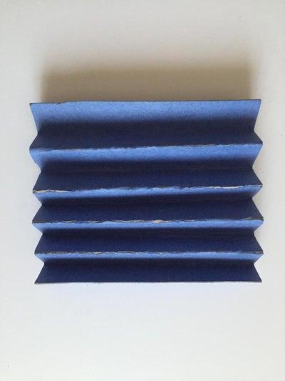
- Cut two rectangular pieces of 21 x13.5 cm from the cardboard.
- By folding the rectangles on top of each other at certain intervals, we give an accordion shape.
- We paste all our pictures one by one between the two accordion shapes.
- We create a strip with white tape on the outer edges of the accordion.
- We cut the A4 paper to 13.5 width without touching the length and stick it on the back of our final picture.
Step 3: Desing (Part3)
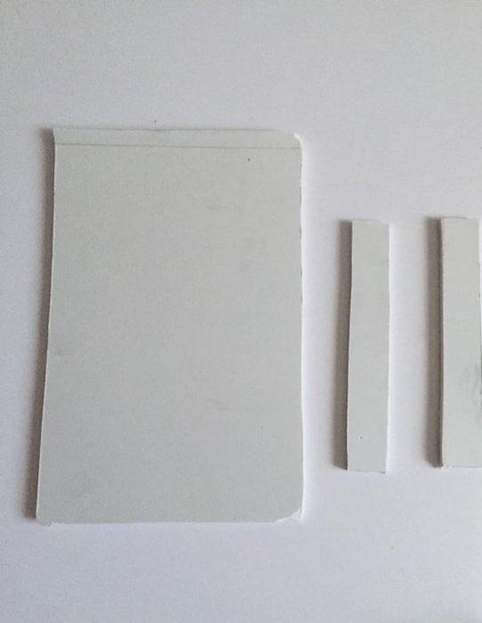
- Cut one piece of 21 x13.5 and two rectangles of 13.5 x 2 from Forex.
- Fix the small rectangles with a silicone gun to form a wall. We open two windows at random two points of the large rectangle.
- We fix the leds on the windowsills and pass them through the window by inserting their cables.
- We fix the light (ldr) sensor to the lower part of the LEDs. We connect its cable and pass it through one of the windows. This design will be our led wall.
- In the design with our pictures, we stick our led wall to the excess part of the A4 paper that we paste on the back section. Thus, we will obtain a system that can be opened and closed.
- Let’s make the connections. We fix the Pinoo control board behind the led wall. We connect our red led to the purple input number 1, our green led to the purple input number 2, and our light sensor to the red input number 7 with our connection cable.
Step 4: Connection
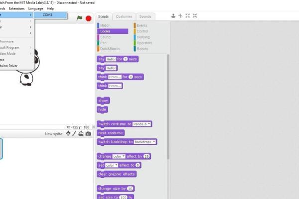
- We have completed our connections, now let’s move on to the coding part. For this we will use the Mblock-3 application.
- Let’s connect our Pinoo control card to the computer with the help of a connection cable and enter the Mblock3 application. Then, let’s introduce our Pinoo control card to the computer. To do this, we first click on the serial port option from the Connect tab. Then we select COM3. (The number may differ according to the computer and the port.)
- After making the serial port connection, let’s select the card we will use from the Cards tab. We are working with Arduino Nano model.
- In order to add the Pinoo extension to our computer, we click on the ‘Manage Extensions’ option from the Extensions tab. In the window that opens, we type “Pinoo” in the search engine and just click download to the result. It has been installed on our computer.
- We come to the Extensions tab again and click on the Pinoo option. We will write our codes with the Pinoo extension.
Step 5: Coding (Part1)
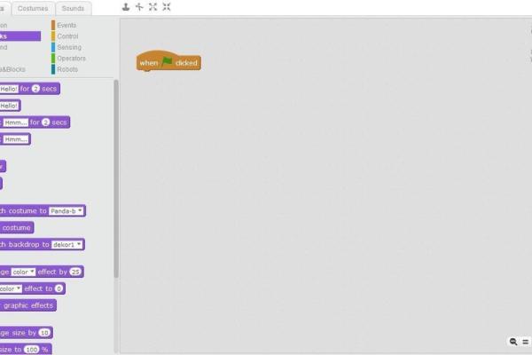
- In the coding part; To start the application, we get the code when clicking the Green Flag from the Events menu.
- We will get help from variables in order to learn the value read by the light sensor. In the Data & Block tab, we create a variable named light.
- Since we want all the code blocks we will write to run continuously until we stop them, we get the block of code from the Control tab continuously.
- We need to specify that the light variable we created is equal to the value read by the light sensor. From the Data & Block tab, we take the code block, let the light be 0, and from the Robots tab, we place the code block related to the light sensor in the 0 (value) section.
- Do not forget to change the pin number. We made the sensor connection to the Pinoo7 input.
- We click on the green flag and we can observe the values of the light in the upper left corner. You can leave the light sensor in light and dark with your hand and observe the values it takes, take a note.
Step 6: Coding (Part2)
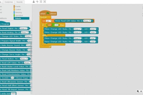
- Let us set the threshold value of the sensor as 200 for the closing of the book (You can change this threshold value as you wish according to your project) and create the necessary condition conditions. For this, firstly, we take the block if it is not from the Robots tab.
- If the light is less than 200, we create our condition statement by taking the less than block from the Transactions tab and the light statement from the Data & Block tab to create the statement.
- In case the condition is fulfilled, that is, if the book is closed, we want our red and green LEDs to light up. From the Robots tab, we take the code block for the LED and change the pin: Pinoo1.
- In order to enable the green LED that we connected to the Pinoo2 input to light, we take our code block related to the Led again from the Robots tab and update it as pin: Pinoo2.
- In the case where the cover of the book is open, that is, if the light sensor is illuminated, we will use the part of our condition / condition block ‘’if not’’. In this section, both of our LEDs should not light. First of all, for the red LED, we take the code block for the LED from the Robots tab and change the pin: (Pinoo1) and the LED part to LOW.
- In order to ensure that the green LED that we connected to the Pinoo2 input does not light, we take our code block related to the led again from the Robots tab and update the pin: Pinoo2 and the LED part as LOW.
- After completing our codes, we check the operation of our project by clicking the green flag. We close the book and create a dark environment for the sensor. Our red and green LEDs should be lit at this stage. Then we open the cover of the book. Our leds must be dead.If there is no problem in the operation of our project, we need to load the codes we have written into our card in order to run it with a power source independent of the computer.
- For this, click the green flag we used at the beginning and throw away the code and get the Pinoo program code from the Robots menu.
- Right click on the code and click on Upload to Arduino. (We work with Arduino as a board.)
- We are waiting for the codes to be uploaded to the card. After the installation is complete, we close the window.
Step 7: Project Working
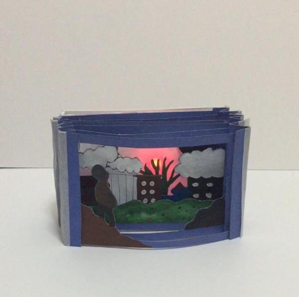
If there is no problem, we disconnect our power cable from the computer. We power our Pinoo control board with the help of a 9v battery and a battery cap. We also turn the ON/OFF button right next to the battery input to the ON position.
Source: Tunnel Book With Pinoo