Summary of Tom the Tortoise Thief
Summary: Built a slow, 8-servo quadruped controlled by an ESP32 webserver to belly-flop and pick up items with sticky tape. Printed parts house servos and an ESP32 on stripboard, powered servos with 4 AAs (ESP32 via cable), and used Python on a PC to send websocket commands. Custom gaits and servo-control code handle walking, turning, and a slam pick-up action. Design and assembly choices, limitations, and code excerpts are described.
Parts used in the Tom the Tortoise Thief:
- 8 small servos (TGY-90)
- ESP32 devkitC (soldered onto copper stripboard)
- 4 AA batteries or lithium ion battery with buck/boost converter for servos
- Power cable or lithium ion battery with converter for ESP32
- 2x 8-pin headers
- 2x 6-pin headers
- Small screws (7mm long, ~1.45mm diameter used)
- Sticky material for bottom (3M brown packaging tape folded)
- Double sided tape
- Normal tape
- Hot glue or super glue
- Thin grippy rubber for feet
- Many small wires
- Zip ties
- Switch
- 3D printer (or access to one)
- Paper for making the shell
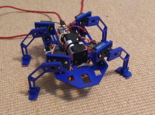
I had 8 small and really old servos, as well as an ESP32 that was soldered onto a copper stripboard. I therefore decided to make a walking quadruped that would have something sticky on it’s stomach, allowing it to pick things up secretly when it belly flopped, (Like a card).
Because I only had 8 servos I could not use the normal 3 servos per leg that quadrupeds and hexapods use, I would be stuck using only 2 per leg. This combined with quadrupeds having a much harder time balancing than hexapods due to the gait, meant that it was destined to be slow from the start. (On the flipside, no-one ever expects a tortoise to run off with their credit card, so it always gets away).
In addition, most ESP32s have wifi, so we can control the bot from a PC. A lithium ion battery is best to power the ESP32 for this use because it won’t be limited by the range of a cable. I was planning on using a 3.7V lithium ion battery combined with a boost converter, however the converter I had was not operational. I was therefore forced to use a cable to power the ESP32.
I contolled it by running a webserver on the ESP32, then sending instructions from a PC using Python. The project was a weekend project, so some bits are rushed and could be optimised.
Supplies
- 8 small servos, I used TGY-90s, these are old and were bought in 2014
- ESP32 devkitC (Must have wifi), mine was soldered onto a copper stripboard before I got it.
- 4 AA batteries or a lithium ion battery with a buck/boost converter for the servos
- Either a lithium ion battery with converter, 4 AAs, or a cable to power the ESP32
- 2x8pin and 2×6 pin headers
- Lots of small screws, I used 7mm long and 1.45mm diameter screws. In hindsight these were too thin and had a tendancy for the head to snap off.
- A sticky thing to go on the bottom, I just used 3M brown packaging tape folded on itself.
- Double sided tape
- Normal tape
- Hot glue/ Super glue
- Thin grippy rubber
- Lots of small wires
- Lots of zip ties
- A switch
- A 3D printer, or access to one
- Paper to make the shell
Step 1: Design the Parts
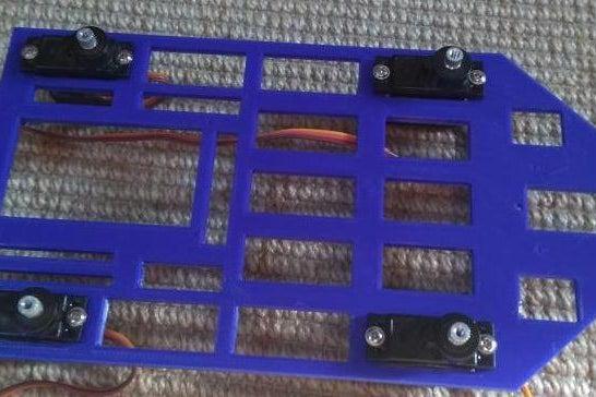
The last image is the servo. From this we can see that we have two mounting holes at the base of the servo, in addition we have a plastic piece on top of the servo that we will attach to.
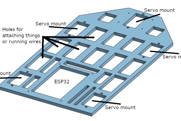
The base plate has 4 servo mount holes at the edges, with one at the front. I originally added this front hole as a way of either attaching a servo for a head, or as another leg. Another leg would improve the stability of the bot, but I did not have enough servos for this. The holes for the screws here are 2mm, that being the correct size for the screws that came with the servos.
At the back there is one big hole where the ESP32 will be mounted, there are small holes at all 4 corners of this hole where the copper board will be mounted using small screws. These holes are 1mm, but would work better as 1.5mm in hindsight, this is because the plastic expansion from the print made the hole smaller than the designed hole.
Step 2: Print the Parts
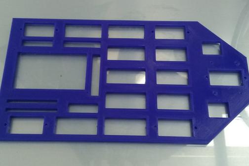
The parts were printed on a creality CR-10. The legs and feet took about 50 minutes each, the hip part took about 28 minutes each and the main body took just under 3 hours. On the hip and leg you can see the plastic piece that fits on top of the servos.
I screwed the foot and the leg together. I then added some double sided tape to the bottom, allowing me to add some rubber which should help with the grip on smooth surfaces.
Step 3: Solder Headers Together
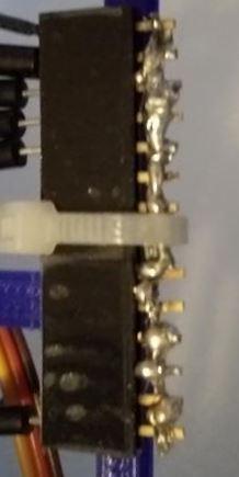
I apologise for the horrible soldering in advanced. This really could be improved, and adding a shrinkwrap over the top would prevent any shorts in the circuit.
In this step I soldered an 8 pin header and a 6 pin header together to make a 14 pin rail. I did this once again to make 2 rails. The rails let me connect all the servos to the batteries by connecting the battery to the rail, then the servos to the rail. This is repeated for the ground, the only difference is that the ground also attaches to the ESP32s ground as well as the battery ground.
Step 4: Start Assembling the Bot
Assembling the bot was done in this order:
- Place the servos into the body of the bot and screw them in
- Place the ESP32 mounted on a copper stripboard onto the bot, this was then screwed in
- 4 AA batteries were zip tied to the frame of the bot. These will power the servos.
- The rails were zip tied on the side of the bot
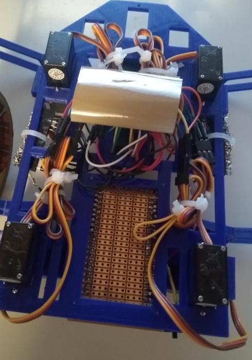
- The servos were then connected into both rails, then after that, the GPIO pins of the ESP32. I stuck with the pins between 13 and 33. This is because 0-12 are used for specfic things, like outputting PWM signals on boot. The Pins 34-39 are input only, so you can’t use them.
- I ziptied the cables onto the bottom of the bot, this is pretty ugly, but the servo cables are long, sothere isn’t a nice way to do this.
You can see the holes I added to the bot have come in useful, we can run cables from the bottom to the top side of the bot. We can also zip tie stuff like the battery to the bot.
Step 5: Finish the Assembly of the Bot
The last steps in assembling the bot are:
- Attach the hips, these are the pieces that sit on the servo that is in the main body
- Place a servo in the hips and screw it in
- Place the leg into this servo on the hips
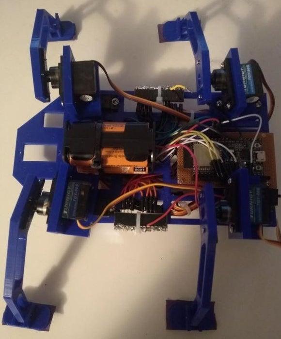
- I added a switch to the bot. This was wired between the battery positive and the positive rail, this let me control whether the servos were on or off. This was done using super glue in my case.
- The last image shows an oversight with the design. When the back left leg moves, it goes over the ESP32 and blocks some pins. I fixed this by bending the pins, but a better solution would be making the body wider so the hip doesn’t go over the esp32
The hardest bit about this step is making sure that the legs are all connect to the same degree on each servo. This means that you could attach them looking straight, but if the servos are at different positions you will need to remove them and remount them on properly.
Step 6: Add Sticky Thing
I just chose 3M scotch packaging tape, I just cut a section off and wrapped it around until I had DIY double sided sticky tape.
All we need to do is belly flop the bot to pick things up and run off with. So this solution works great for us.
Step 7: Working Out Gaits
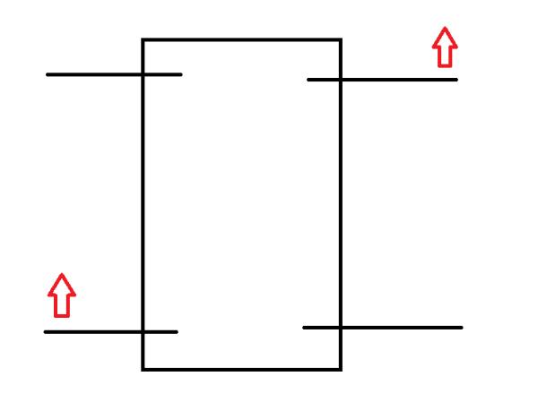
Gaits are very hard for quadrupeds, this is because unlike hexapods when they lift a leg they are unstable. Quadrupeds normally lift diagonal limbs, balancing on the other two limbs. However my bot only has two servos per leg, meaning that there is less control than a normal quadruped. Therefore we will only move one leg per time, this means the bot needs to be able to balance when only one leg is lifted.
The images show the gait the quadruped will use:
- It will move a diagonal pair of legs (Not at the same time).
- It will move all legs back, pushing the whole body forward. The first pair have returned to their starting position.
- It will reset the other diagonal leg pair which have moved back.
- It has now reset to the starting position
The reason we move the first pair is because if we don’t, the bot is too front heavy when it moves all the legs back and cannot reset the legs. Therefore, the best way to maintain stability is to try and make sure at least one opposite pair is in the starting position.
This same procedure is followed for turning the bot. The only difference is that in the opposite pair, we move one leg forward and one leg back. Afterwards we turn the servos on one side one direction, and the servos on the otherside the other direction. This results in the bot turning it’s body.
Step 8: ESP32 Code
We now start the ESP32 code. (I did notice I named the servos, “motors” many times in the code, this doesn’t affect the output). If you haven’t already, you can follow a guide like this: https://randomnerdtutorials.com/installing-the-es…
This guide will show you how to setup the arduino IDE to use the ESP32, mine came preloaded with arduino, so not flashing was required.
The imports are shown below:
#include <Servo.h>
#include "WiFi.h"
#include "ESPAsyncWebServer.h"
We use the default servo library, and the wifi library. In addition we import the WebServer library for the ESP.
const char* ssid = "Test";
const char* password =  "Test1234";
Next we set the name of the wifi and the password for the wifi. This will tell the ESP what wifi to join.
IPAddress local_IP(192, 168, 137, 100);
IPAddress gateway(192, 168, 1, 1);
IPAddress subnet(255, 255, 0, 0);
These next three variables allow us to set IPAddresses that we want to use. This lets the ESP to have a static IP, very useful so you know the IP when you want to connect to it.
AsyncWebServer server(80);
AsyncWebSocket ws("/test");
These two lines sets the port (80 is the default http port) and the location. In this case just “/test”.
char receivedChar;
boolean newData = false;
The receivedChar variable lets us store the most recent character that has been received by the ESP, in addition the newData lets us check whether anything was recieved since we last checked.
Servo servos[8];

int servo_pins[8] = {13, 14, 26, 27, 19, 32, 21, 33};
int servo_offset[8] = {0, 0, 20, 0, 0, 5, 10, 0};
int current_motor_position[8] = {60, 60, 60, 60, 120, 120, 120, 120};
These lines define 8 servo objects, the servo pins, the current position of the servos, and the offset for the servos. I had to add offset because these were cheap servos and didn’t all have the same positions for the same values.
int servo_move_speed = 5;
int body_move_speed = 7;
These two values are millisecond delays. The first being how many milliseconds the ESP should wait between each degree of movement of the legs. The second value is the same as the first, but only applies when the 4 body servos are moving, we want to go slower here to maintain grip on surfaces.
void setup() {
  Serial.begin(115200);
  for(int i = 0; i < 8; i++){
    servos[i].attach(servo_pins[i]);
    delay(50);
  }
  reset_servos();

  if (!WiFi.config(local_IP, gateway, subnet)) {
    Serial.println("STA Failed to configure");
  }

  WiFi.begin(ssid, password);

  while (WiFi.status() != WL_CONNECTED) {
    delay(1000);
    Serial.println("Connecting to WiFi..");
  }

  Serial.println(WiFi.localIP());

  ws.onEvent(onWsEvent);
  server.addHandler(&ws);

  server.begin();
}
This is the setup. It opens a serial for debugging, and initialises and resets the servo positions to their starting postions.
It then configures the wifi and tries to connect to the wifi hotspot. It will only continues on if it manages to connect.
void onWsEvent(AsyncWebSocket * server, AsyncWebSocketClient * client, AwsEventType type, void * arg, uint8_t *data, size_t len){
  if(type == WS_EVT_CONNECT){
    Serial.println("Websocket client connection received");
  } else if(type == WS_EVT_DISCONNECT){
    Serial.println("Client disconnected");
  } else if(type == WS_EVT_DATA){
    Serial.println("Data received: ");
    receivedChar = data[len-1];
    Serial.println(receivedChar);
    newData=true;
    Serial.println();
  }
}
This function is an asynchronous handler for the wifi, this lets use recieve signals even when a delay() is currently udnergoing. This stops instructions being missed. If it recieves data it sets it to the most recent character, and sets the “newData” bool to true.
void loop() {
  parse_new_instructions();
}

void parse_new_instructions() {
  if (newData == true) {
    if(receivedChar =='w'){
      move_forward();
    }
    if(receivedChar =='a'){
      turn_left();
    }
    if(receivedChar =='d'){
      turn_right();
    }
    if(receivedChar =='k'){
      slam();
    }
    newData = false;
  }
}
The loop just calls the function, “parse_new_instructions”. In this function it checks if the “newData” bool is true, if it is, it checks what it is and calls the corresponding action function.
void move_motor(int motor, int new_position, int delay_time){
  current_motor_position[motor] = new_position;
  if(motor<=1 || (motor>=4 && motor<=5)){
    new_position = 90 + (90-new_position);
  }
  servos[motor].write(new_position+servo_offset[motor]);
  delay(delay_time);
}
This is the simplest way to move a servo, and the servo goes straight to the end position with no delay. It does check that if the servo is mounted the opposite way, to flip the end position. This is because 60 degrees means the opposite direction depending if the servo is on the left or right side of the bot. It just flips them so 60 degrees means the same on both sides.
void move_motor_delay(int motor, int new_position){
  int difference = new_position - current_motor_position[motor];
  for(int i = 0; i<abs(difference); i++){
    int current_position = current_motor_position[motor];
    if(difference>0){
      current_position = current_position + i;
    } else{
      current_position = current_position - i;
    }
    if(motor<=1 || (motor>=4 && motor<=5)){
      current_position = 90 + (90-current_position);
    }
    servos[motor].write(current_position+servo_offset[motor]);
    delay(servo_move_speed);
  }
  current_motor_position[motor] = new_position;
}
This function does the same as before, but allows the bot to put a delay inbetween each degree of movement. This slows down the movement of the servos, stopping whiplash through the bot which may unbalance it.
void move_motors(int end_positions[], int delay_time){
  int counters[4] = {0, 0, 0, 0};
  int difference[4];
  int start_positions[4];
  int highest_difference = 0;
  for(int motor =0; motor<4; motor++){
    start_positions[motor] = current_motor_position[motor];
    difference[motor] = end_positions[motor] - start_positions[motor];
    if(abs(difference[motor])>highest_difference){
      highest_difference = abs(difference[motor]);
    }
    current_motor_position[motor] = end_positions[motor];
  }
  for(int i = 0; i<highest_difference; i++){
    for(int motor =0; motor<4; motor++){
      if(counters[motor] <= abs(difference[motor])){
        int current_position = start_positions[motor];
        if(difference[motor]>0){
          current_position = current_position + i;
        } else{
          current_position = current_position - i;
        }
        if(motor<=1){
          current_position = 90 + (90-current_position);
        }
        servos[motor].write(current_position+servo_offset[motor]);
        counters[motor] += 1;
      }

    }
    delay(delay_time);
  }
}
This last way to move the bot moves the four servos in the body at the same time. This is great for when we want to push the bot forward. This is hardwired for only controlling the servos in the body, and you must supplying positions for each of them. This could easily be expanded for the servos in the hips as well, but I didn’t feel the need for this.
void reset_servos(){
  move_motor(0, 60, 50);
  move_motor(1, 60, 50);
  move_motor(2, 60, 50);
  move_motor(3, 60, 50);
  move_motor(4, 120, 50);
  move_motor(5, 120, 50);
  move_motor(6, 120, 50);
  move_motor(7, 120, 50);
}
To reset the bot, we just set the servos back to their starting positions.
void move_forward(){
  Serial.println("Moving Forward");

  //Move right front leg forward
  move_motor_delay(4, 160);
  move_motor_delay(0, 20);
  move_motor_delay(4, 120);

  //Move back left leg forward
  move_motor_delay(7, 160);
  move_motor_delay(3, 20);
  move_motor_delay(7, 120);

  //Move all legs
  int end_pos[4] = {60, 100, 100, 60};
  move_motors(end_pos, body_move_speed);

  //Move front left leg forward
  move_motor_delay(6, 160);
  move_motor_delay(2, 60);
  move_motor_delay(6, 120);

  //Move back right leg forward
  move_motor_delay(5, 160);
  move_motor_delay(1, 60);
  move_motor_delay(5, 120);

  reset_servos();
}

void turn_right(){
  Serial.println("Turn right");
  //Move right front leg back
  move_motor_delay(4, 160);
  move_motor_delay(0, 100);
  move_motor_delay(4, 120);

  //Move back left leg forward
  move_motor_delay(7, 160);
  move_motor_delay(3, 20);
  move_motor_delay(7, 120);

  //Move all legs
  int end_pos[4] = {60, 20, 100, 60};
  move_motors(end_pos, body_move_speed);

  //Move front left leg forward
  move_motor_delay(6, 160);
  move_motor_delay(2, 60);
  move_motor_delay(6, 120);

  //Move back right leg forward
  move_motor_delay(5, 160);
  move_motor_delay(1, 60);
  move_motor_delay(5, 120);

  reset_servos();
}

void turn_left(){
  Serial.println("Turn left");
  //Move right front leg back
  move_motor_delay(4, 160);
  move_motor_delay(0, 20);
  move_motor_delay(4, 120);

  //Move back left leg forward
  move_motor_delay(7, 160);
  move_motor_delay(3, 100);
  move_motor_delay(7, 120);

  //Move all legs
  int end_pos[4] = {60, 100, 20, 60};
  move_motors(end_pos, body_move_speed);

  //Move front left leg forward
  move_motor_delay(6, 160);
  move_motor_delay(2, 60);
  move_motor_delay(6, 120);

  //Move back right leg forward
  move_motor_delay(5, 160);
  move_motor_delay(1, 60);
  move_motor_delay(5, 120);

  reset_servos();
}

void slam(){
  Serial.println("Slamming!");

  move_motor(4, 160, 50);
  move_motor(5, 160, 50);
  move_motor(6, 160, 50);
  move_motor(7, 160, 50);

  delay(1000);

  move_motor(4, 120, 50);
  move_motor(5, 120, 50);
  move_motor(6, 120, 50);
  move_motor(7, 120, 50);
}
These last four functions are actually just telling the servos how and when to move. At the end of each one I reset the servos, just to be sure that everything has reset correctly.
If you want to read more about the wifi or webserver, you can find information here: https://techtutorialsx.com/2018/08/14/esp32-async-…
Source: Tom the Tortoise Thief
- How many servos does the project use?
The project uses 8 small servos. - Can the ESP32 be controlled wirelessly?
Yes, the ESP32 runs a webserver and is controlled over WiFi from a PC. - What power sources were used for the servos and ESP32?
The servos were powered by 4 AA batteries; the ESP32 was powered via a cable because the boost converter was not operational. - How are the servos wired together for power?
Two combined header rails (made from soldered 8-pin and 6-pin headers) were used as power and ground rails to connect the servos to the battery. - What gait strategy does the quadruped use to remain stable?
It moves one leg at a time using diagonal leg pairs and ensures at least one opposite pair stays in the starting position to maintain stability. - Which GPIO pins on the ESP32 were used for servos?
Pins between 13 and 33 were used; pins 0-12 and 34-39 were avoided for the reasons described. - Does the project include code for walking, turning, and slamming?
Yes, the ESP32 code implements move_forward, turn_left, turn_right, and slam functions. - How is stickiness added to the robot for picking items?
DIY double sided sticky tape was made by folding 3M packaging tape and applied to the belly. - Are servo offsets accounted for in the code?
Yes, an array of servo_offset values corrects positional differences between cheap servos. - What methods are used to move servos smoothly?
The code includes move_motor_delay and move_motors functions that step servo angles with small delays to slow movement and reduce whiplash.