Summary of Teclado MIDI Super Simple – Super Simple MIDI Keyboard
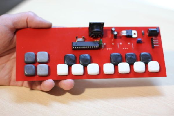
This tutorial details the step-by-step construction of a standalone, one-octave MIDI keyboard programmable via Arduino using an ATmega328p. The process involves designing and etching a custom PCB using ferric chloride, soldering electronic components, and assembling 16 pushbuttons with SUGRU for a tactile finish.
Parts used in the One Octave Arduino MIDI Keyboard:
- Atmega328p with Arduino bootloader
- 28 leg socket
- Crystal 16Mhz
- Capacitors 22 pF
- Capacitors 10 uF
- Capacitor 0.1 uF
- Regulator 7805
- Female Power plug for PCB
- Female DIN 5 (MIDI) Connector for PCB
- 90° male pin headers
- SPDT switch or vertical Male pin headers and a jumper
- Pushbuttons
- Resistor 10k
- Resistor 220 ohm
- One layer copper board
- Ferric chloride
- Spray Paint
- SUGRU packages
Este tutorial te lleva paso a paso por la construcción de un teclado MIDI de una octava, programable via arduino gracias a su conector de 6 pines. Vas a necesitar:
 Componentes:
- 1 Atmega328p con el bootloader de Arduino
- 1 Zócalo de 28 patas
- 1 Cristal 16Mhz
- 2 Capacitores 22 pF
- 2 Capacitores 10 uF
- 1 Capacitor 0.1 uF
- 1 Regulador 7805
- 1 conector de alimentación hembra para placa
- 1 Conector DIN 5 (MIDI) hembra para placa
- 6 pines macho 90°
- 1 switch inversor simple (SPDT) para placa (o 3 pines macho verticales y un jumper)
- 16 pulsadores para placa
- 1 resistencia 10k
- 1 resistencia 220 ohm
Circuito:
- Placa de cobre virgen (una capa) de 20 x 10 cm
- Cloruro férrico (250 cm3)
- Recipientes plásticos
- Pintura en aerosol
Botones:
- 3 sobres de SUGRU blancos
- 3 sobres de SUGRU negros
This tutoria shows how to build a 1 Octave Standalone Arduino programmable MIDI keyboard. You’ll need:
- 1 Atmega328p with Arduino bootloader
- 1 28 leg socket
- 1 Crystal 16Mhz
- 2 Capacitors 22 pF
- 2 Capacitors 10 uF
- 1 Capacitor 0.1 uF
- 1 Regulator 7805
- 1 Female Power plug for PCB
- 1 Female DIN 5 (MIDI) Connector for PCB
- 6 90° male pin headers
- 1 SPDT switch por PCB or 3 vertical Male pin headers and a jumper
- 16 pushbuttons
- 1 10k resistor
- 1 220 ohm resistor
Circuit:
- 1 One layer copper board (20 x 10 cm)
- Ferric chloride (a small bottle)
- Plastic containers
- Spray Paint
Buttons:
- 3 White SUGRU packages
- 3 Black SUGRU packages
Step 1: PCB 1
Si bien no es el objetivo de este tutorial, enseñar a hacer circuito impreso, vamos a pasar por cada paso. Si alguien necesita más información, hay varios tutoriales dedicados a construcción de PCB acá en Instructables.
1)Descargá el archivo de fritzing:
,2) Exportá el circuito en formato PDF e imprimilo en una impresora láser, usando papel ilustración (no modifiques su tamaño!)
1) Cortá (de una placa virgen de cobre de una capa) un pedazo de 20 x 7 cm.
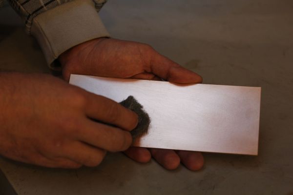
2) Eliminá huellas dactilares, manchas y demás impurezas usando un pedazo de lana de acero
3) Recortá la impresión y colocala boca abajo sobre la placa
4) Calentá la plancha y colocala sobre el papel y presioná sin mover por unos segundos para que la impresión se adhiera a la placa.
5) Presioná con los bordes de la plancha haciendo movimientos circulares. Continúa hasta que veas el circuito a través del papel.
6) Sumergí la placa en agua y dejala por 30 minutos para que la pulpa del papel se ablande.
7) Sacá la placa del agua y comenzá a retirar con cuidado el papel de la placa
8) Todo resto pequeño de papel puede ser retirado con la ayuda de un escarbadiente o similar. La tinta quedará adherida a la placa. Es muy importante que retirés el papel de los agujeros por los que pasan los componentes ya que eso ayuda a la mecha (broca) a alinearse y perforar correctamente.
9) Es probable que en el proceso hayas levantado alguna que otra traza. Si no son muchas, podés volver a dibujarlas con un marcador indeleble. Si son demasiadas, no te preocupés. Es normal las primeras veces, simplemente retirá todo con la ayuda de la lana de acero y volvé a comenzar desde el paso 2.
——————————————————————————–
Altough the purpose of this tutorial is not to show how to make PCB, we’ll show it step by step. If you need more info, you can search through Instructables to see dedicated tutorials for PCB making.
1) Download and open Fritzing file.
2) Export circuit as PDF and print it in Laser Printer using glossy paper (don’t modify its size!)
1) Cut a 20 x 7 cm (7,87 x 2,75 inches) piece of one layered copper board
2) Remove fingerprints, dust, spots, etc. using iron wool.
3) Cut the print and put it over the board (ink towards copper).
4) Heat the Iron, put it over the paper and press gently without moving for a few seconds. This will stick the paper to the board.
5) Start moving the iron (using its borders) in circles, pressing all the time. After a few minutes, all the circuit will be revealed smoothly through the paper.
6) Put the board in water and wait for about 30 minutes for the paper to soften
7) Take the board out of the water and start removing all the paper. Ink will remain stick to the copper
8) Every small remainder of paper must be removed, using a toothpick or similar. Even the small holes in the traces.
9) It’s probable that you also remove some ink traces. If they are not too many, you can draw them again using a permanent ink marker. If they are too many, don’t worry! (it happens a lot a the first time) Remove every trace of ink and paper using iron wool, dry the board and start again from step 2.
Step 2: PCB 2
Una vez que tu placa está lista, es hora de “comer” el cobre que no queremos. Para ello usamos Cloruro Férrico. Es importante que tomés precauciones:
- No trabajes en presencia de niños (y mantené la botella cerrada lejos de su alcance).
- Elegí un lugar ventilado.
- Usá guantes (o algún elemento protector como una bolsa)
- No tires excedentes de cloruro férrico en cañerías. Volvé a embotellarlo ya que podés usarlo muchas veces!
- Usá ropa vieja. Donde el cloruro cae, mancha para siempre.
- No uses recipientes que luego destinarás a almacenar comida.
- No tengás miedo al manipularlo, simplemente sé precavido.
Ahora estamos listos:
- Calentá la botella de cloruro férrico a baño maría durante unos 10 minutos en agua hirviendo
- Apoyá la placa sobre el fondo de un recipiente y derramá el contenido de la botella hasta cubrirla por completo
- Cada 5 minutos, podés tomar la placa (usá guantes o una bolsa!) y ver como va. Cada tanto podés sacudir levemente el recipiente para mejorar el contacto entre el cloruro y la placa
- En un día templado tu placa debería estar lista en unos 15 minutos. Te darás cuenta porque al sacarla ya no habrá ningún rastro de cobre en las superficies expuestas.
- Limpiá los excedentes de cloruro usando papel de cocina. Cuando esté completamente seca, podés limpiarla con agua y secarla.
- Tu placa está lista para ser perforada. Antes de esto, vamos a pintar con alguna pintura en aerosol la cara que no tiene el circuito, sólo para que se vea mejor 😉
———————————————————————————————
- Once the board is ready, it’s time to etch. Since we’re using ferric chloride, it’s important to take some precautions
- Don’t etch boards in presence of kids (and store the bottles away from them!!!)
- Chose a ventilated or open space
- Use gloves (or even a plastic bag) to protect your hands
- Don’t pour remaining acid on the drain! Store it again in its plastic bottle. You can use it many times!
- Use old clothes. FeCl3 stains will remain forever
- Don’t use container where you usually store food. Remember also that they must be made plastic or glass (not steel!)
- Don’t be afraid, just be cautious
Now we’re ready:
- Heat the FeCl3 Bottle in a double boiler for about 10 minutes.
- Lay the board in the bottom of the container and cover it with the hot FeCl3
- Every 5 minutes, grab the board (using gloves or a plastic bag) and see how it’s going. From time to time, shake smoothly the container.
- In a warm day, the board should be ready in about 15 (it depends also on the times you’ve used the same FeCl3). You’ll realise when it’s ready because you’ll see no copper at all (just the ink).
- Clean the remaning FeCl3 with paper. Then you can clean the board with water. Dry it with a cloth
- Your board is ready. Now we will paint it (using any spray paint) to make it look better.
Step 3: Perforar y soldar – Drill and solder
Con la placa lista, es momento de perforar. Con una mecha de 0,8 a 1 mm, podrás hacer todos los agujeros de los componentes, excepto el conector de alimentación y las pestañas de agarre de los potenciómetros verticales y el conector MIDI.
Colocá un cartón fino debajo de la placa para no rayar la pintura y realizá todas las perforaciones.
Al momento de soldar, podés usar la imagen de serigrafía de Fritzing (incluida abajo) para orientarte. Ahí están incluidos los valores de los componentes (en la introducción está la lista completa). Atención a la dirección en la que se coloca el zócalo y luego el Atmega 328, el regulador de voltaje y también a la polaridad en capacitores electrolíticos (10uF) y el diodo de protección (justo al lado del conector de alimentación). No olvides también soldar los dos jumpers o puentes (en azul en la imagen de Fritzing).
En la foto no verás los potenciómetros verticales (no se consiguen en Argentina) pero están ruteados en la PCB a las entradas A4 y A5.
—————————————————————————————————–
Once the board is ready, it’s time to drill. You can use a 1⁄32 to 3⁄64 bits (sorry if conversion is not OK) for every component hole except from power plug and MIDI and Potentiometer “hooks”. Place a thin cardboard under the board to avoid scratching the painting.
Use the image below to guide you through soldering components. There you can see values and orientation (complete BOM in Intro page). Pay atention to orientation in socket (and, of course, microcontroller), voltage regulator, and also polarity in electrolytic capacitors (10 uF) and diode. Don’t forget to solder jumpers (a clipped resistor leg will do). They are marked blue in the image. You won’t see the vertical 10 pots in the picture (we don’t get those in Argentina) but they are properly routed to A4 and A5 (with 5V and GND on each extreme leg).
For more detail: Teclado MIDI Super Simple – Super Simple MIDI Keyboard
- How do I prepare the copper board for etching?
Print the circuit on glossy paper using a laser printer, place it ink-side down on the cleaned copper board, and transfer the design using a hot iron. - What safety precautions are required when using ferric chloride?
Work in a ventilated area, wear gloves, keep children away, avoid pouring acid down drains, and use old clothes that can be stained permanently. - How long does the etching process take?
In warm weather, the board should be ready in about 15 minutes, indicated by the absence of exposed copper traces. - What size drill bit should be used for component holes?
Use a 0.8 to 1 mm drill bit for all component holes except for the power plug and connector mounting tabs. - Can I make mistakes while transferring the circuit to the board?
Yes, minor trace errors can be fixed with a permanent marker, but significant errors require removing the paper and starting over from cleaning the board. - Do I need to paint the back of the PCB?
Painting the side without the circuit is optional but recommended to improve the appearance of the board. - Where are the vertical potentiometers routed if not visible in photos?
The vertical potentiometers are routed to inputs A4 and A5 with 5V and GND on each extreme leg. - What material is used to create the button caps?
White and black SUGRU packages are used to mold the buttons for the keyboard.