Today’s spacecraft subsystems require an increasing number of power rails and supply distributions with loads ranging from milliamps to tens of amps. It is important to choose the appropriate solution to meet the performance and reliability requirements for the target mission.
Switched-mode power supplies (SMPS) use energy storage elements such as inductors, capacitors or transformers to transfer energy from the input to the output at periodic intervals. In a SMPS, transistors are operated in their low-dissipative switching states instead of active mode as used by a linear regulator. When a transistor is on and conducting, the voltage drop across its power path is minimal, and when it is off, there is almost no current through the power path.
Inductors, capacitors and transformers are reactive components and given ideal parts, a SMPS could achieve power conversion and regulation with 100% efficiency. All power loss is due to non-ideal components and deficiencies in the control circuitry.
Inductors are fundamental to the design of switch-mode regulators described in this post, particularly their tendency to initially resist a change in current by establishing an induced voltage whose polarity opposes this change. An a.c. current through a coil induces a voltage across it as a result of the changing magnetic field, whose direction counteracts the change, i.e., it opposes the source for an increasing current and aids for a decreasing current.
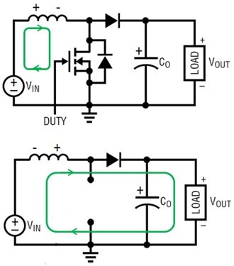
The basic circuit topology for a Buck (step-down) converter together with its input and output currents and voltages are shown below. The direction of the inductor/load current is highlighted in green.
When the FET switch is opened, the source is removed but current must continue to flow through the inductor and load in the same direction with the free-wheeling diode now providing the return path. The voltage across the magnetic becomes VOUT, but its polarity reverses to aid the source, with the inductor current decreasing with a slope equal to -VOUT/L. The stored energy in the magnetic field is discharged through the load.
For a Buck converter, the output, load current is continuous while the input current pulses, which has implications for input and output filtering.
For more detail: Switch-mode regulators for space applications