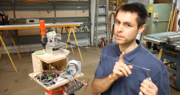
The cable is wound on a retractable spool, and passes over a pulley and through a carbon fiber tube mounted on a two-axis gimbal. There are a few commercial machines that use this mechanical approach, but [Scott] decided to build one himself after seeing the prices. The angle of rotation of each axis of the gimbal and the length of extended cable is measured with encoders, and in theory the relative coordinates of the probe can be calculated with simple geometry. However, for the level of precision [Scott] wanted, the devil is in the details. To determine the position of a point within 0.5 mm at a distance of 3 m, an angular resolution of less than 0.001° is required on the encoders. Mechanical encoders could add unnecessary drag, and magnetic encoders are not perfectly linear, so optical encoders were used. Many other factors can also introduce errors, like stretch and droop in the cable, stickiness of the bearings, perpendicularity of the gimbals axis and even the spring force created by the encoder wires. Each of these errors had to accounted for in the calculations. At first, [Scott] was using an Arduino Mega for the geometry calculations, but moved it to his laptop after he discovered the floating point precision of the Mega was not good.
[Scott] spend around 500 hours building and tuning the device, but the end result is really impressive. There are surprisingly few optical machines that can achieve this level of precision and accuracy, and they can be affected by factors like the reflectivity of an object.If you do want to get into real 3D scanning, definitely take the time to read [Donal Papp]’s excellent guide to the practical aspects of the various technologies. Most of us already have a 3D scanner in our pocket in the form of a smartphone, which can be used for photogrammetry.
Source: SUB-MM MECHANICAL 3D SCANNER WITH ENCODERS AND STRING
