Summary of Starting with ATTiny13
Summary: The article promotes using ATTiny13A microcontrollers for simple, low-cost electronics projects instead of Arduino. It outlines five benefits—cheap, versatile, small, energy efficient, and challenging—then guides making a simple ATTiny13A breakout PCB, setting up a programming environment, and writing an AVR assembly program. The author provides Eagle CAD files and printable PDFs for a breakout board with six GPIOs, power LED, pull-up/reset circuit, and soldering recommendations.
Parts used in the ATTiny13A Breakout Project:
- ATTiny13A-SSU microcontroller
- 1K resistor (for power indicator LED)
- SMD LED (power indicator)
- 10K resistor (pull-up for RESET)
- RESET switch (2-pin SMD or equivalent)
- Headers or pads for 6 GPIO pins
- VCC and GND connections/traces
- PCB (Eagle CAD .brd and .sch files provided)
As any beginner electronics hobbyist I have recently came to conclusion that using Arduino(or even Mega328) for small projects is neither cost-effective or educational (I’ll explain why later).
Another reason for writing this article is that I came across few ATTiny13A-SSU chips @ less than $0.90 each, which is even lower the official retail price, so I just had to buy 5 of them, although I didn’t know at the time whattahellamigointodowithit what is it really capable of.
I’ve decided to dive into some info on entry-level AVR microcontrollers and come to find out there are some cool and equivalently complex projects built with ATTiny-family ICs. Basically, if you need to make something simple, like blink a few LED’s or control a pair of relays for your smart appliance, while keeping your expenses at bay – this material will be very useful to you.
 WHY?
WHY?
So, why do I think that ATTiny is better than your Arduino for small projects? Well, there are at least 5 reasons:
1) Cheap. An average retail price is >$1.00/piece, but you might get lucky(as I did) and get it even cheaper. In contrast, a close equivalent “Trinket Mini” (Tiny85-based board) from Adafruit will cost you $6.95.
2) Versatile. You can use it with almost any simple peripheral extensions (w/ some reasonable limitations), including 16×2 LCD, HC-05 module, sensors, keypads, etc.
3) Small. You can minimize most of your permanent little projects to the size of a matchbox with little to no extra effort.
4) Energy efficient. ATTiny13A uses at most [email protected] (5V) and can go as low as 240μA@1MHz with 1.8V supply.
5) Challenging. 1KB flash and 64B RAM will teach you some good practices of writing an efficient code. Plus, you’ll get something to brag about
So, enough chat. We have some great things to make!
On today’s agenda:
- Building a simple breakout board for ATTiny13A-SSU MCU
- Setting up a programming environment
- Writing our first program in AVR assembly
MAKING A PCB
I’ve already compiled a detailed tutorial on making custom PCB, which is available here. The only additional info I can provide at this point is that you could create your own design which will fit your own needs using Eagle CAD. Remove a RESET button, if you need an additional IO pin, or add a few debugging LEDs to IO pins – whatever suits you.
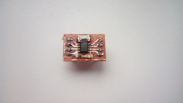
I will attach sample breakout board with 6 GPIO pins, power indicator LED and a hardware reset button. You may add a few debugging LEDs to I/O pins the same way, or make duplicate pins for each of 6 GPIOs, if you are planning to use multiple things on the same I/O line, but at this point I’m just trying to keep it simple.
As you can see, at the bottom there is an SMD LED with 1K resistor (serves as our power indicator). And at the top we have a 10K pullup resistor, which connects VCC and RESET pins, combined with a RESET switch, which in its turn connects to the GND pin of ATTiny.
I did not find any suitable 2-pin SMD buttons in Eagle, so I just used a resistor of an equivalent size as a placeholder.
The download link for both board/schematic and PDF files are right below:
Tiny13 PCB (Eagle CAD .brd, .sch)
NOTE: Remember to disable all unused layers before printing (leave Layer1 and green landing pads). Don’t forget to enable “Mirror” and “Black” in Eagle print dialog.
Soldering components together is fairly easy even with a regular soldering iron, but I would still recommend using a hot-air soldering station for surface-mounted components in order to avoid headaches and component damage.
For more detail: Starting with ATTiny13
- Why choose ATTiny13A over an Arduino for small projects?
The article lists five reasons: cheaper, versatile with simple peripherals, smaller size, energy efficient, and it encourages writing efficient code due to limited memory. - What files are provided to make the breakout PCB?
The author provides Eagle CAD .brd and .sch files and a ready-to-print PDF. - How many GPIO pins does the sample breakout board expose?
The sample breakout board exposes 6 GPIO pins. - What components are used for power indication and reset on the board?
A SMD LED with a 1K resistor is used as a power indicator, and a 10K pull-up resistor with a RESET switch is used for reset. - Can I remove the RESET button to get an extra IO pin?
Yes, the article suggests you can remove the RESET button if you need an additional IO pin. - What soldering method is recommended for SMD components?
While soldering with a regular soldering iron is possible, the author recommends using a hot-air soldering station for surface-mounted components. - Do I need to change any print settings before printing the PCB PDF?
Yes, remember to disable unused layers, leave Layer1 and landing pads, enable Mirror and Black in Eagle print dialog. - Is ATTiny13A suitable for peripherals like LCDs or HC-05 modules?
The article states ATTiny can be used with almost any simple peripheral extensions with some reasonable limitations.