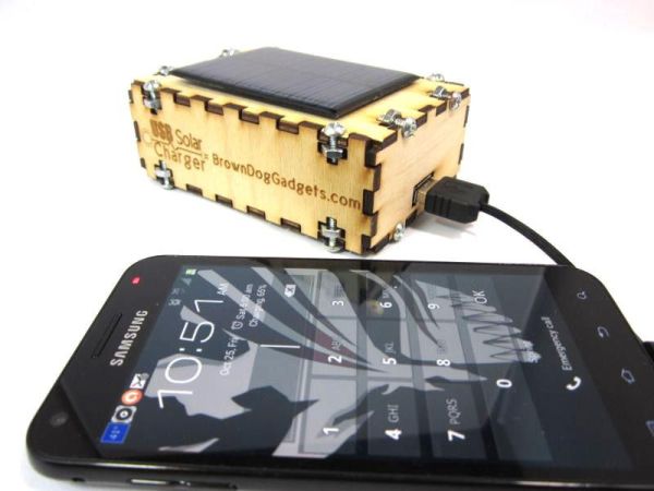
Everyone has USB gadgets. It’s pretty much a fact of life. Another fact of life is that these USB gadgets also continually run out of power when you most need them. No need to fear, solar power is here! Ditch those crazy wall adaptors, throw out the laptop, and start making your own solar charger!

One of the most popular projects for new Makers is creating their very own Solar USB Charger. While there are many right ways to do this, there are also many highly inefficient ways. In 2011 I posted deigns on how to put a simple USB charger in an Altoids tin. While this proved to be a very useful and fun project that design hasn’t held up well over time. With each new generation of cell phone or MP3 Player batteries get bigger and my original design proves to be less useful.
This guide will show you step by step instructions on how to make your own Solar USB Charger as well as files on how to make a nice looking laser cut wooden box. This charger will charge most small USB devices such as cell phones, mp3 players, iPods, and iPhones. These direction are designed to use parts from my Solar USB Charger 2.0 Kit though you can also find many of these parts elsewhere online. You can also choose to ignore the laser cut wooden case aspect and use a different enclosure, though I’d recommend not using Altoids tin anymore.
This project was designed for beginner Makers and students. It requires a base knowledge of soldering. While you can charge small gadgets, this project is not appropriate for camping or to be relied on for extreme emergencies.
Difficulty: Easy
Cost: Low
Time: 30 – 60 minutes
Step 1: Parts and Tools
Major Components in Project
All parts for this project, as well as a complete DYI kit, can be found atBrownDogGadgets.com.
Parts:
DC to DC Boosting Circuit with 5V USB Output
6V Solar Cell
3 x Rechargeable NiMh AA Batteries
3 AA Battery Holder
1N914 Diode
Toggle Switch
Wire – Stranded
Shrink Tubing
Wooden Case Parts:
1/8th Inch Plywood
16 x 6-32 Screws
16 x 6-32 Hex Nuts
Tools:
Soldering Iron
Solder
Wire Cutters
Wire Strippers
Double Sided Foam Tape
Screw Driver
Optional Tools:
Electrical Tape
Hot Glue Gun
Helping Hand
Access to a Laser Cutter
Step 2: Boosting Circuit
USB need 5V at around 500mA of power to charge most gadgets. There are two ways to make a Solar USB Charger.
One way is to get a solar cell with a very high voltage and then drop it down to 5V. This requires a very big solar cell. If you wanted to add a battery into the mix you’d need to make sure it was also above 5V, which would mean a big battery. All in all you’re going to make one heavy and expensive charger.
The other way is to use a lower voltage and than boost it up to 5V. This allows for a smaller solar cell and smaller batteries. The downside is that you sacrifice amperage for voltage. This is the most common way for small commercial USB chargers to provide power as this decreases size, weight, and cost.
The key to this whole operation is a DC to DC Boosting Circuit. Also known as a Transformer. Using a coil of wire this basic circuit boosts the voltage up to 5V while also providing some power regulation and stability. In the case of our circuit the output for this is a USB port.
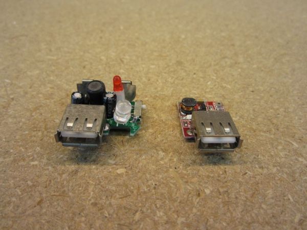
Above are two different, yet very similar, DC to DC Boosting circuits. They both take voltages as low as 2V and boost them up to 5V. The difference only really matters if you’re using an older Apple product. Typically a USB gadget requires just power from a USB port to charge. Most iPhone models, however, require a tweak to USB to work. iPhones will check the USB data ports in order to identify what kind of device it’s plugged into and change charging speeds if it thinks the port can support it. Unfortunately if it doesn’t see anything on the data tabs it will refuse to charge. This is a problem that plagues many generic USB chargers, especially older ones.
If you don’t have an iPhone or iPod, then any old DC to DC Boosting circuit with a USB port will work. If you do have an iPhone or iPod you may wish to grab one of these charging circuits, as they’re the only ones I’ve found that seem to work.
Step 3: Solar Cell and Batteries
Our DC to DC Boosting circuit needs a minimum of 2V to operate, so we need to choose power sources with this in mind.
Battery Power
I always advise the use of power storage when doing a solar project. Solar is inconsistent due to the inconsistent nature of the sun. Even though the sun may look and feel stable, the power coming out of our solar cell is always fluctuating to some degree. Using batteries helps stabilize the flow of power, and also lets us hold onto that energy for later use.
In this project we’re using simple rechargeable AA batteries. Three to be exact. Rechargeable batteries put out 1.2V of power and by using three we’re able to achieve 3.6V. This seems to be the ideal setup. Using only two batteries our voltage drops below 2V too quickly, and by using four batteries we end up needing a much larger solar cell.
The biggest downside to using AAs is that there is no easy way to monitor their charge. You’ll never know when they’re completely full. The easiest way is to just estimate using the input from the solar cell and the capacity of the batteries. (Yes, you could wire in a small voltage meter and secondary power supply, but that makes this project quite a bit more complicated and more expensive.)
Solar Power
When charging batteries we need a minimum voltage to get the batteries to charge. As long as we have the minimum the batteries can accept the amperage (current). A higher voltage does not make the battery charge faster. As a general rule of solar you always want to provide 1.5 times the voltage you really need. Again, due to the inconstant nature of solar, we need some wiggle room. Our battery source is 3.6V and using a 6V solar cell is more than enough.
Amperage (current) is the aspect of electricity that pushes electronics into our batteries. Like all batteries ours uses a chemical reaction to store energy and comes with some special rules of it’s own. When charging a AA battery using a wall adaptor we’re able to charge them a very high speed due to smart chips that constantly monitor the battery. As our circuit is “dumb,” with nothing to monitor the batteries, we’re going to have to trickle charge the batteries using the 10% rule. AAs can be safely charged as long as they don’t have more than 10% of their capacity thrown at them at any one time. This means that 2,000mAh batteries can only have 200mA of current thrown at them via solar.
As our solar cell is only 80mA we’re completely safe. One good aspect of the trickle charge method is that it can never over charge our batteries. Once they’re full they’ll just stay topped off.
Step 4: Circuit Diagram
Above is a circuit diagram for this project. It’s designed so that the solar cell is always charging the batteries and the toggle switch turns the USB circuit on/off.
A diode has been put in place to prevent power from flowing the wrong direction into the solar cell.
This is a very common diagram for solar. This basic setup can easily be scaled up or down depending on the project.
Step 5: Laser Cut Case
For this project I have designed a laser cut wooden box. The box fits every part perfectly. My box is made of 1/8th inch Baltic Birch plywood. I’ve included the file in this project in case you have access to a laser cutter. If you’re really outgoing try painting, staining, or varnishing the laser cut wood.
If this isn’t an option for you there are more simple ways of making an enclosure. A simple plastic food container or bin works wonders. If possible find one with a rubber o-ring as it’ll help keep moisture out. These types of bins are ideal as they’re inexpensive, easily found, and also are easy to modify.
It’s also possible to find “Project Boxes” at many online stores. These also work quite well for enclosures, but tend to cost more.
It’s best not to use any metal enclosures if at all possible. Such things as Altoids tin or mint tins may look nice, but can easily short out projects and are quite difficult to modify.
Step 6: Solder The Solar Cell
Cut three six inch strips of wire.
Using a wire stripper, strip off about 1/4th an inch on all ends. (You can also do the battery pack as well at this time.)
Take two pieces. Solder one to the Positive tab on the solar cell and one to the Negative tab on the solar cell.
If you’re using a laser cut case, apply foam tape to the bottom of the solar cell. Leave the protective film on the tape. We won’t be securing it until the end.
For more detail: Solar USB Charger 2.0

