
Summary of Make A 0 to 99 Light Display Using Arduino
This article describes building a 0-99 LED display using an Arduino that reads light levels via a photoresistor. The system maps light intensity to a two-digit number shown on seven-segment displays, utilizing custom wiring techniques with staples and sandpaper to connect segments between the displays.
Parts used in the 0-99 Light Display:
- Photo resistor
- Arduino
- 9 different wires
- 2 seven segment led displays
- Bread board
- Staples
- Fine grit sandpaper
- Stapler
This circuit will take a light reading then display a number between zero and 99.
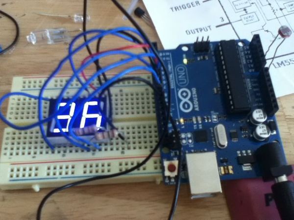
Step 1: Parts you will need
Major Components in Project
To make the 0-99 LED display you will need…
~ photo resister
~ Arduino
~ 9 different wires
~ 2 seven segment led displays
~ bread board
~ staples
~ fine grit sandpaper
~ and a stapler
Step 2: The Code
This is the code for the Arduino
I tried to explain it the best I could in the comments but I ran out of room in some of them
so lines of interest
int pinstringA[11] {
HIGH,LOW,HIGH,HIGH,LOW,HIGH,HIGH,HIGH,HIGH,HIGH};
these strings code for the state of one segment each so
pinstringA[0] == HIGH this means that when the number is zero segment A is High
light = map(light, 0, 1024, 100, 0);
the pullup resister flips the values of the photo resister so a lot of light makes the number low
so I Changed the scale from 0 to 1024 to 0 to 100 then flipped it.
tens = light / 10;
This finds the tens value eg. 19/10= 1 remainder 9 the remainder is then thrown out
the line below saves the remainder for the ones place
PORTD = PORTD & B00000011;
This turns all the pins on port d off but leaves pin 0 and 1 alone (for serial communication)
see http://arduino.cc/en/Reference/PortManipulation for more details
Step 3: STAPLES!!?!
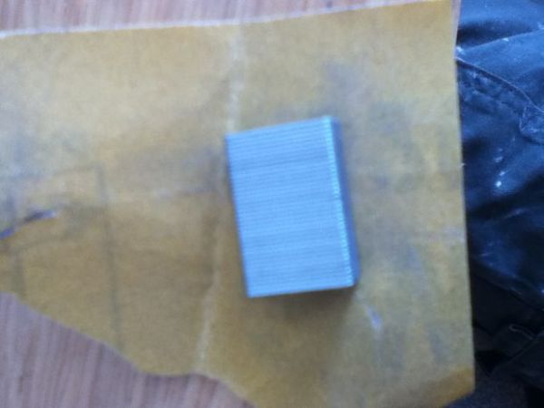
With the code downloaded you need to connect the board
you need to connect the corresponding pins together so pin one
of one display connects to pin one of the other display
Staples works very well for this they are six pins in length the only
bad part is that the glue that holds them together is non conductive so
take the sandpaper and rub off the glue on the downward leads
next pop them in a stapler and use it to push the actual staples apart
push them into the bread board leaving room for the display and wires
to connect to Arduino.
Step 4: Attach wires
Attach wires to the led.
Step 5: Connect to Arduino
Connect each wire to the Arduino.
Segment A to pin 4
B to 7
C to 8
D to 6
E to 3
F to 2
and G to pin 5
Also connect ground from ones place to pin 9
and ground from tens place to pin 10
Last connect the photo resister to the Arduino ground and Analog 0
For more detail: Make A 0 to 99 Light display Using Arduino
-
How does the code handle light values?
The code maps light values from 0 to 1024 to a scale of 100 to 0, flipping them because the pullup resistor causes high light to result in low numbers. -
What is the purpose of the sandpaper in this project?
Sandpaper is used to rub off the non-conductive glue from the downward leads of the staples to ensure conductivity. -
Why are staples used instead of soldering?
Staples are used to connect corresponding pins of the two displays together because they are six pins in length and work well for this connection. -
Which Arduino pin connects to Segment A?
Segment A is connected to pin 4 on the Arduino. -
How does the code calculate the tens value?
The code divides the light variable by 10 to find the tens value, discarding the remainder which is then saved for the ones place. -
Where should the photoresistor be connected?
The photoresistor must be connected to the Arduino ground and Analog 0. -
What command turns off specific pins on Port D?
The line PORTD = PORTD & B00000011 turns all pins on port d off but leaves pin 0 and 1 alone for serial communication. -
How do you prepare the staples for use?
You push the staples into a stapler and use it to push the actual staples apart after removing the glue with sandpaper.
