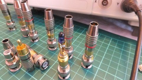
A while ago we came across a website on infrared remote controls which suggested a simple way to view IR signals using an Oscilloscope. The idea is to use a standard IR Led mounted into a BNC/RCA plug using a spare channel making an Oscilloscope infrared receiver. So we set about ordering the connectors, which arrived in the post today. Another way of looking at this device is as a ‘poor-mans’ IR receiver, but if you have an Oscilloscope to plug it into then maybe you are not so poor after all.
The idea is to shine your IR remote control on to the IR Led while pressing a key which results in a small amount of current passing through the IR LED. This in turn creates a voltage differential across the terminals of the Led. For this to work well, you need to have the emitter of the remote control right up against the IR LED of the receiver.
To construct this device, the pins of the IR LED are soldered to the connector with the cathode (-) being connected to negative and the anode (+) being connected to the positive terminal. To get cleaner falls on the signal solder a 22K ohm resistor across the legs of the IR Led. The resistor value isn’t critical as we tried several values down to 7K ohms and didn’t notice any appreciable difference in signal quality. We were pleasantly surprised at the fidelity of the signal, as long as you hold your remote control steady and in position.
In our tests we were consistently able to display & trigger signals on the screen of the oscilloscope with 1 volt peaks, with ease. Another benefit of this approach is that there is no additional noise creeping in from external power supplies.
For more detail: ‘Silver bullet’ – the Oscilloscope Infrared Receiver

