Summary of Sigh Collector
This project builds a home monitoring system that detects a user's sighs via a wearable chest-strap sensor and wirelessly triggers a stationary unit to briefly inflate a large red air bladder as a physical visualization of sighing. It includes electronics (Arduino, xBees, op-amp), a hacked rechargeable air pump with a check valve, a constructed wooden enclosure, and a latex or balloon bladder. Detailed steps cover materials, circuit hacking and programming, enclosure fabrication, bladder casting, and assembly.
Parts used in the Sigh Collector:
- 1, 4x8 Sheet of Plywood (shop-grade maple ply used)
- 2, 2x2 for structural frame
- ~2 yards of red nylon strap fabric
- Loose red fabric from a fabric store
- Latex tubing (Inner Diameter: 1/8", Outer: 1/4")
- Wood Screws (5/16, 3", 4")
- 1 Rechargeable battery powered air pump (Coleman Rechargeable Quick-Pump)
- 1 unidirectional check valve
- A piece of garden hose
- Liquid Latex and red pigment, or a large red balloon
- 1, 20cm Stretch Sensor
- 1 red RCA cable, male and female headers
- 1 10K Potentiometer with large knob
- 1 3-way toggle switch
- 2 Arduino Microcontrollers (Diecimille or newer)
- 2 9V battery clips with 5mm center-positive male jacks
- 2 xBee wireless modules
- 2 xBee shields from LadyAda
- 1 FTDI cable for programming the xBees
- 1 LMC662 rail-to-rail OpAmp chip
- TIP120 transistor (implied in motor drive)
- Miscellaneous electronic components as per circuit diagrams
and immediately expel it; to make a deep single
audible respiration, especially as the result or
involuntary expression of fatigue, exhaustion,
grief, sorrow, or the like.
[1913 Webster]
These are instructions for building a home monitoring system that measures and ‘collects’ sighs. The result is a physical visualization of the amount of sighing, for personal use in a domestic environment. The project is in two parts. The first part is a stationary unit, which inflates a large red air bladder upon receiving the appropriate signal. The second part is a mobile unit, worn by the user, which monitors breathing (via a chest strap) and communicates a signal to the stationary unit wirelessly when a sigh is detected.
1. You have a basic understanding of construction and fabrication techniques,
as well as access to the appropriate tools and facilities.
2. You have a working knowledge of physical computing (reading circuit diagrams)
3. You are overwhelmed with the anxiety of living in a failing state, and frustrated
that most of your household objects address only physical rather than emotional health.
Step 1: Material Needed
Each individual page has more details and links on where you can purchase some of these materials. Physical Materials:
> 1, 4×8 Sheet of Plywood. I used a piece of shop-grade maple ply.
> 2, 2×2 for the structural frame
> ~2 yards of red nylon strap fabric
> Some loose red fabric from a fabric store
> Latex tubing (Inner Diameter: 1/8″, Outer: 1/4″)
> Wood Screws ( 5/16, 3″, 4″ )
> 1 Rechargeable battery powered air pump (Coleman Rechargeable Quick-Pump)
> 1 unidirectional “Check Valve”
> A piece of a garden hose
> Liquid Latex & Red Pigment, or a large red balloon of some kind. Electronics, Misc:
> 1, 20cm Stretch Sensor
> 1 red RCA cable, Male and female headers
> 1 10K Potentiometer with large sized knob
> 1 3-way toggle switch
> 2 Arduino Microcontrollers (Diecimille or newer)
> 2 9V battery clips with 5mm (center positive) male jacks.
> 2 xBee wireless modules
> 2 xBee shiels from LadyAda
> 1 FTDI cable for programming the xBees
> 1 LMC662, “rail-to-rail” OpAmp chip
> Misc Electronics components (see circuit diagrams for details).
Step 2: Build and Program Circuit. Hack into Air Pump
I like to start by getting the electronics working first, usually with a prototype of what I want to build (made from cheap exterior plywood, or even cardboard and hot-glue).
The electronics are divided into two parts. This part is the receiving end. It will receive a wireless signal from the wearable unit and use that signal to turn an air pump on for ~2 seconds and then turn it off.
Between the pump and balloon, is what’s called a check valve, which lets air pass one direction but not the other.
The air pump is a Coleman Rechargeable “Quickpump”. I like it because of the rechargeable battery, and the different sized nose attachments.
Open up the pump and rework the toggle switch, so that it’s bridging between the battery and one terminal of the motor. The other terminal of the motor will run to the collector of the TIP120 transistor. To do this, you’ll have to de-solder the black wire from the second motor terminal, and also de-solder the lead coming from the battery charger and going to the other end of the toggle switch. Be sure to common ground the motor’s battery with the Arduino’s power supply.
Build the circuit in the diagram below. There is also a PDF attached for higher resolution.
Program the Arduino with the code supplied in the text file. You’ll need to install this library.
If you don’t know how to work with Arduino, here are some references so you can learn:
> Main Arduino Website
> Freeduino — Repository of Arduino knowledge and links
> NYU, ITP’s in-house physical computing site with tutorials and references.
Step 3: Build the Sigh Collector main unit
For the sake of brevity, I will not detail every step in the process of building the main unit. Suffice it to say that it can be as simple or complex as you wish; anything from cardboard and hot glue to custom fabricated or more advanced materials.
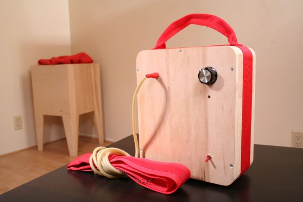
I have designed mine this way, which isn’t to say it’s the only way it could be done. If you care to follow or elaborate on my instructions, see the diagram below. Again, a higher resolution PDF is attached. On the diagram, you will find exact measurements and specifications on how to build the unit pictured below.
As stated in Step 2, I built mine out of shop-grade Maple plywood. It has a nice grain and cuts well. I left the surface raw.
A couple design notes:
I decided to drive all the screws in from the inside so that you wouldn’t see them from the exterior. It can be tricky to sneak a drill inside of the unit, so I recommend building it in sections. I angled the bottom edges of the 2×2 frame, so that they would look a little sleeker when visible.
The top piece with the mitered corners and circular opening is removable, for easy repair of inside parts. The pump and electronics will sit inside the box, on a shelf that is held up by two of the 2×2’s on the inner frame (see diagram).
The reason I built it on a frame is so that the corners would stay square. Otherwise, plywood can tend to warp. This way, also, everything can be held together by screws and therefore broken down easily into pieces.

Step 4: Make the air bladder
Step 5: Combine electronics with main unit. Install Check Valve and Pump
Place the air pump and circuit inside of the main unit, on the lower shelf. Now it’s time to make a connection between the air pump, and the air bladder/balloon, which will sit on the surface.
We only want air to go one way, and not come out the other direction, so we use something called a “check valve”. The basic principle is that a hinged door, rubber diaphragm or ball is displace by air going one way, but then prevents the air from going back.
For more detail: Sigh Collector
- What does the project do?
It detects a user's sighs with a wearable chest strap and wirelessly triggers a stationary unit to inflate a red air bladder as a visualization. - How is the air bladder made?
The author cast a bladder by brushing layers of liquid latex mixed with red pigment onto a large balloon; alternatives include a beach ball or garbage bag. - How does the stationary unit get triggered?
The wearable unit sends a wireless signal via xBee to the receiving Arduino, which turns the air pump on for about two seconds. - Which air pump is used and why?
A Coleman Rechargeable Quick-Pump is used for its rechargeable battery and interchangeable nose attachments. - What modification is required on the air pump?
Open the pump and rework the toggle switch so it bridges battery and one motor terminal, desolder the black wire from the second terminal, and route the motor through a TIP120 transistor, sharing common ground with the Arduino supply. - Why is a check valve used?
To allow air to pass into the bladder but prevent air from flowing back out. - What electronics are required on the wearable unit?
A stretch sensor (20cm), Arduino microcontroller, xBee module and shield, power supply, and associated circuitry to detect sighs and send signals. - Do you need woodworking skills for the main unit?
Yes; the main unit is built from plywood and 2x2 framing with specific cuts and assembly details, though simpler materials could be used.