Summary of Sense Magnetic Fields Like a Bird – Sensory Extension Puppet
This project details the construction of "Compy," a wearable puppet equipped with GMR magnetic sensors to detect field direction and strength. The Arduino Nano processes sensor data to drive a 3x3 haptic display of vibration motors, providing tactile feedback. Developed at CU Boulder's Craft Tech Lab, the build involves embedding sensors in the beak, soldering components, and hiding electronics within the puppet's body to create a sensory extension tool.
Parts used in Compy Puppet:
- Long back puppet
- 9 ERM vibration motors
- Arduino Nano
- Protoboard
- 2 GMR sensors from NVE
- 2 PCBs from NVE
- Heat shrink tubing
- Stiff felt
- Silicone wire
- Hot glue
- Hot glue gun
- Needle and thread
- Solder and soldering iron

This project will show you how to create a computationally enriched puppet that can detect magnetic fields. The puppet (who I call Compy) has two very sensitive GMR analog magnetic sensors that are located in her beak, these sensors are read by an Arduino Nano that actuates a 3×3 haptic display (Figure 3) based on the sensor readings.
While wearing Compy, you will be able to detect magnetic fields and identify their general direction and strength!
This project was developed in the Craft Tech Lab and ATLAS Institute at The University of Colorado, Boulder.
If you have any questions, want to keep up with my work, or just toss around ideas, please do so on my Twitter: @4Eyes6Senses. Thanks!
Step 1: Materials
1x Long back puppet (mine is from the Puppet Company)
9x ERM vibration motors
1x Arduino Nano
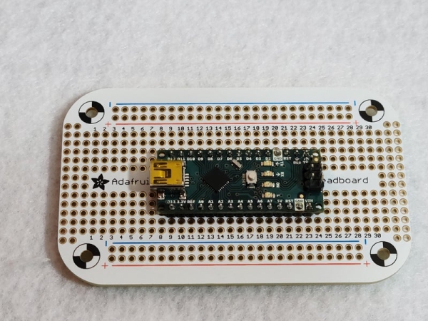
1x Protoboard (I got mine from Adafruit)
Heat shrink tubing
Stiff felt
Silicone wire
Hot glue
Hot glue gun
Needle and thread
Solder and soldering iron
Step 2: Soldering the GMR Sensors to the PCBs
I went with a GMR (giant magneto-resistive) sensor because it is much more sensitive than a Hall-effect sensor. It’s also an application of nanotechnology, which I think is neat.
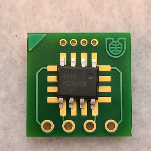
– Make sure that your NVE GMR sensor and PCB are oriented correctly. This part is vital, so triple-check that the orientation is the same as figure 1, confirm that the dimple on the sensor is in the corner nearest to the logo and on the side with the smaller pins.
– Carefully solder the legs of the GMR sensor to the board (Figure 2). I suggest that you start with one leg on each side of the sensor so that it won’t move while soldering the rest.
– Solder the silicone wire to the pins on the PCB. Be VERY generous with the wire length, I did about 2 feet for each pin. I went with the color scheme red (VCC), yellow (A0 for sensor 1 & A2 for sensor 2), blue (GND), and green (A1 for sensor 1 & A2 for sensor 2).
– Attach heat shrink to the cables so that the cables are secure near the PCB pins (Figure 3 & 4).
– Attach heat shrink over some of the sensor and PCB so that the rest of the cables are secure to the board (Figure 5).
– Heat and secure the heat shrink.
Step 3: Embedding GMR Sensors Into the Puppet’s Beak
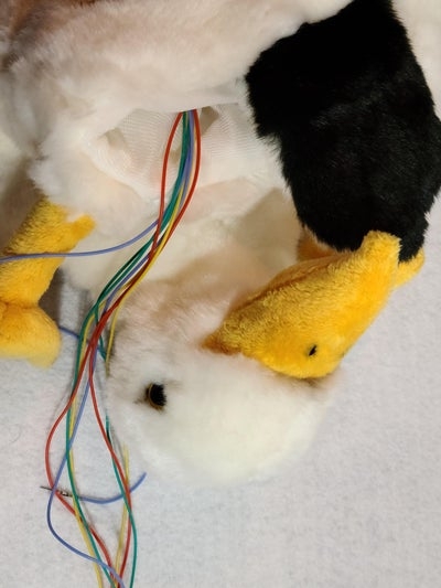
For this step, we will be embedding the sensors inside the puppet’s beak (Figure 1) – one on the inner left side and the other on the inner right side. I found the easiest way to be:
– Turn the puppet inside-out.
– Make a small incision at the top of the puppet’s head.
– Orient the PCB so that the sensor will be facing outward while inside the puppet’s beak.
– Use your fingers to carefully (make sure not to damage the connections between the cables and the PCB’s pins) slide the sensors into the puppet’s beak.
– Repeat until both sensors are in the beak and you are happy with their placement. Your puppet should look similar to figure 2.
– Sew the incision shut.
– At this step, my puppet looked like figure 3.
Step 4: Soldering the Vibration Motors
In this step, you will be extending the wires on your 9 vibration motors.
– Carefully strip some of the insulation from the vibration motor’s wire. Be VERY careful as it’s very easy to break the wire.
– Solder a wire (red to red or blue to blue) to the wire of the vibration motor. repeat until each wire on all 9 vibration motors has been extended. My wire length was around 8 – 10 inches.
– Isolate one wire from the other, either by adding electrical tape or heat shrink to the exposed wire on the newly soldered connection (between the silicone wire and the wire on the vibration motor). Repeat for each vibration motor.
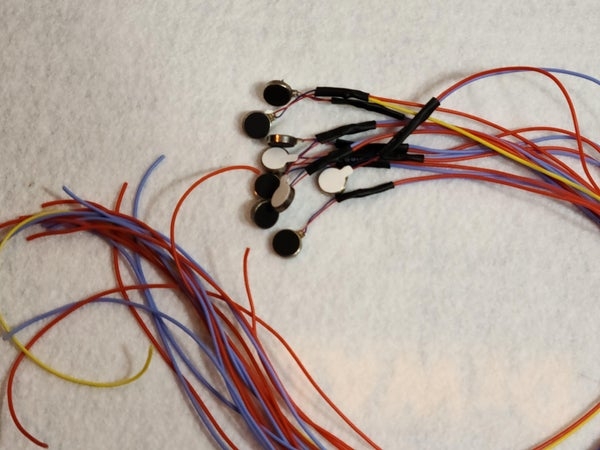
– Add heat shrink to both wires on each vibration motor (Figure 1). Repeat for each vibration motor.
– At this step you should have 9 vibration motors that look similar to figure 2.
Step 5: Creating the Haptic Display
In this step, we will be creating the 3 x 3 haptic display. Spacing between each motor is up to personal choice, I am happy with around an inch to an inch and a half between the motors.
– Cut open the front section of the puppet (Figure 1).
– Cut the stiff felt so that it will cover the inner back of the puppet. Secure the stiff felt to the puppet with hot glue (Figure 2).
– Glue each magnet to the stiff felt so that it looks similar to figure 3.
Step 6: Populate Protoboard and Connect to Microcontroller
For this step, we will connect the sensors and vibration motors to the Nano. Connecting the GRE sensors are straightforward:
For the right sensor (orientation is for when wearing the puppet) solder the red wire to the Nano’s 5V, The blue wire to GND, yellow to A0, green to A1. Repeat for the left sensor but attach its yellow wire to A2 and green to A3.
The vibration motors are when it gets a little tricky.
The vibration motors are laid out as follows (Figure 4):
1 2 3
4 5 6
7 8 9
We want the corresponding motors to be connected to the following digital pins:
D2 D3 D4
D5 D6 D7
D8 D9 D10
– Wire the motors so that they correspond to the chart above (e.g., motor 1 red wire soldered to D2 on the Nano) with 100ohm resistors in series with each motor.
– Wire the motor’s blue wires to the protoboard’s ground bus.
At this point, your protoboard should look similar to figure 5.
Step 7: Hide Wires and Microcontroller
In this step we will hide the wires and microcontroller inside the puppet:
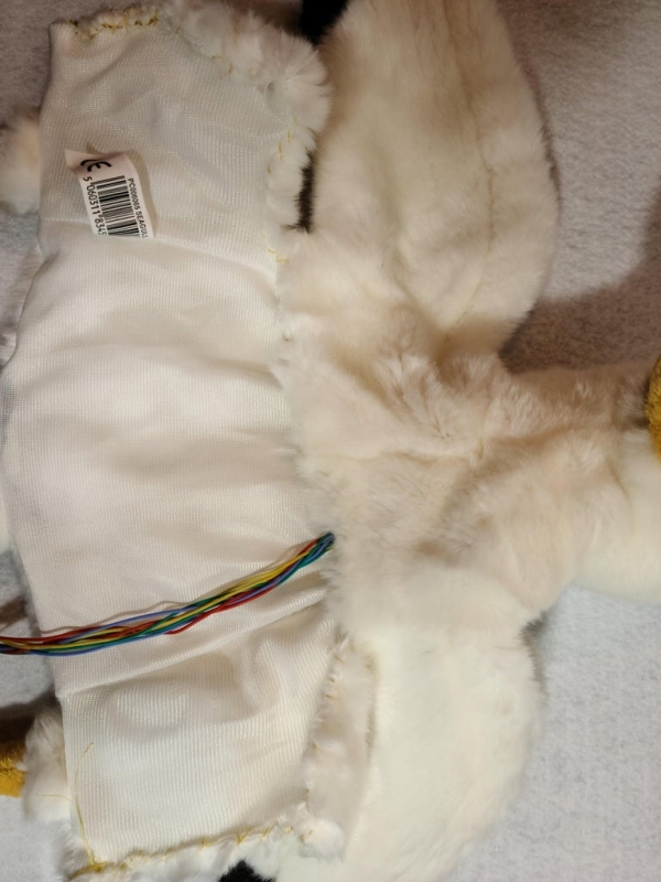
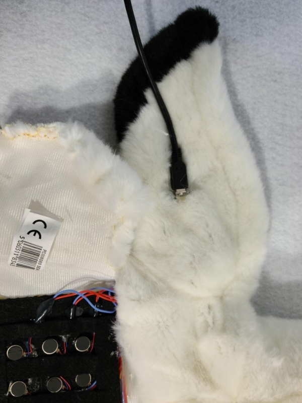
– Place the microcontroller into the wing of the puppet and cut a slit so that the cable can be connected to the Nano (Figure 1). I used hot glue to secure the controller to the puppet and the opening to the controller.
– Use hot glue to hide the wires under the felt square and secure them to the inside of the puppet (Figure 1 before & Figure 2 is the after).
– Cut some additional felt so that you can hide the wires that are connected to the vibration motors (figure 3).
Step 8: Upload Code
For the final step, you will upload the code to the controller. The code has several modes:
1. If both sensors are around the same values, the middle motors (258) will vibrate in an upward pattern.
2. If the right sensor has a higher reading than the left, that means there is a magnetic field to the right of the puppet. I want to actuate the motors so that they make an arrow and are actuated on a sequence, as shown
3(2nd)
5(3rd) 6(2nd) 7(1st)
9(2nd)
3. If the left sensor has a higher reading than the right, that means there is a magnetic field to the left of the puppet. I want to actuate the motors so that they make an arrow and are actuated on a sequence, as shown
3(2nd)
5(1st) 6(2nd) 7(3rd)
9(2nd)
4. If the left sensor is a very high value, I want to indicate this strong field by actuating the middle and left columns, like so:
3 4
6 7
9 10
5. If the right sensor is a very high value, I want to indicate this strong field by actuating the middle and right columns, like so:
2 3
5 6
8 9
6. If both sensors are registering a high value there is a strong magnet that being detected by both sensors. I want all vibration motors to actuate:
2 3 4
5 6 7
8 9 10
Source: Sense Magnetic Fields Like a Bird – Sensory Extension Puppet
- Why were GMR sensors chosen over Hall-effect sensors?
GMR sensors are much more sensitive than Hall-effect sensors. - How should the NVE GMR sensor be oriented on the PCB?
The dimple on the sensor must be in the corner nearest to the logo and on the side with the smaller pins. - What color coding is suggested for the silicone wires connecting to the PCB?
Red is VCC, yellow is A0 or A2, blue is GND, and green is A1 or A3. - How many vibration motors are used in the 3x3 haptic display?
Nine vibration motors are used to create the 3x3 grid. - Which digital pins connect to the vibration motors in the first row?
Motors 1, 2, and 3 connect to digital pins D2, D3, and D4 respectively. - What happens if both sensors register similar values?
The middle motors (2, 5, 8) will vibrate in an upward pattern. - How does the puppet indicate a strong magnetic field detected by only one sensor?
If the left sensor is high, it actuates the middle and left columns; if the right is high, it actuates the middle and right columns. - Where is the microcontroller hidden inside the puppet?
The microcontroller is placed into the wing of the puppet and secured with hot glue. - What is the purpose of adding 100ohm resistors to the motor connections?
Resistors are placed in series with each motor during the protoboard wiring process.