
Summary of (semi) automated drill press table for PCB manufacture
The author automated a manual drill press table to streamline PCB hole drilling by integrating stepper motors with a Proxxon coordinate table. The system uses discrete component motor drivers and an ATMega32u2 microcontroller for USB communication, allowing precise movement based on CAD coordinates.
Parts used in the Automated Drill Press Table:
- Proxxon MICRO compound table KT 70
- Bipolar stepper motors (two units)
- 10mm ratchet wrench sockets
- Metal sheet pieces
- Dremel tool (for cutting slits)
- Metal angles
- Screws
- Small blocks of wood
- FETs for H-bridge circuits
- Perfboard
- ATMega32u2 microcontroller breakout board
Motivation
As you may have seen in earlier articles, I produce my own PCBs at home with the toner transfer method. After some experimentation the PCB quality is quite satisfactory, but drilling the holes for even a moderate number of through-hole components is very tiresome.
When you design your PCBs with a proper CAD software (such as KICAD), you have the coordinates of all drill holes anyway, so how about making an automated moving drill press table which moves the PCB to the places where holes are desired? But calibrating the coordinate system on the PCB should be quick and reliable.
Acquiring a coordinate table and motorizing it
So I got a “Proxxon MICRO compound table KT 70”. The table has two axes with two cranks. At the rear end each axis has a cap that, once removed, reveals a 10 mm hexagon nut. This nut is very tightly attached to the spindle, so it can be used to exert force and move the table.
From pollin.de (surplus store) I got two cheap bipolar stepper motors that I attached to the spindles using 10mm ratchet wrench sockets. I used a Dremel to cut a slit in the stepper motor shaft and inserted a small piece of metal sheet. The other side of the sheet has the exact dimensions to fit diagonally into the square hole of the wrench socket.
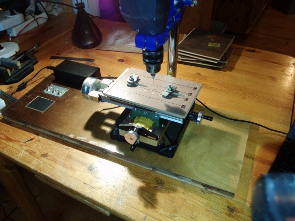
Everything is kept in place with metal angles, screws and small blocks of wood.
I built some motor drivers from discrete components (I didn’t know the good old L298 back then). Each motor has two coils. Each coil is operated with an H-bridge (or full bridge) circuit as shown above. It allows you to pass current in either direction through the coil or turn the coil off completely. There are no protection diodes, because the datasheets of the selected FETs claim that they are already included in the package. I built the driver circuit on a perfboard, because … why not.
Microcontroller + USB + tactile interface
Onto the motor driver board I soldered an ATMega32u2 microcontroller breakout board which I had previously designed and etched. The ATMega32u2 has a native USB interface which can be used to communicate with the microcontroller at runtime, but also to flash the firmware without the need of an extra programmer.
For More Details: (semi) automated drill press table for PCB manufacture
-
Why did the author build this automated table?
To avoid the tiresome process of manually drilling holes for through-hole components after designing PCBs. -
What specific table model was used for the project?
A Proxxon MICRO compound table KT 70 with two axes and cranks. -
How were the stepper motors attached to the spindles?
The motors were attached using 10mm ratchet wrench sockets fitted with custom metal sheets cut from a slit in the motor shaft. -
What type of circuit was used to drive the motors?
H-bridge or full bridge circuits built from discrete components using FETs. -
Why were protection diodes omitted from the driver circuit?
The datasheets of the selected FETs claimed that protection diodes were already included in the package. -
What microcontroller was chosen for the control system?
An ATMega32u2 microcontroller breakout board. -
How does the microcontroller facilitate firmware updates?
It has a native USB interface that allows flashing firmware without needing an extra programmer. -
On what material was the motor driver circuit built?
The driver circuit was built on a perfboard.
