Purpose
This project was built for the Things that Think undergraduate/graduate class CSCI 4830-7 and CSCI 7000-7 for the University of Colorado at Boulder. Our group consisted of one graduate and two undergraduate students. We worked on the project for 8 weeks, most of the time trying to learn how to program the Arduino and learning the basics of circuits. If you are looking to build this project, we do not anticipate this project taking nearly as long, but altogether could be completed in one weekend.
Description
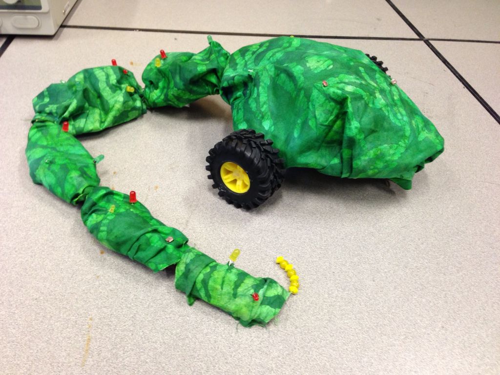
The purpose of this instructable is to outline our development of this robot snake as well as provide instructions and tips for future engineers hoping to complete a similar project or use components of our project in theirs. The goal of this project was to create an automaton snake that reacted to its environment. The main functionality of the snake is for it to follow a light source. Some goals we had in conjunction to the movement of the snake was to have a tail that rattles and decorative LED lighting. This tutorial will start with a little background information, then show the development of the basic pieces, and finish by finalizing your design.
Video of the final product
Tools Needed
Soldering iron, laser-cutter, scissors, sewing needle, small screwdriver, wire cutter/stripper, strong flashlight
Materials Needed
Arduino Uno, Arduino Motor Shield, Breadboard, Wire, Tape, Solder, LEDs, 3 photocell sensors, 2 DC Hobby motors, vibrator motor, Bass Wood, resistors of various resistance, 9V batteries, Toy wheels, string, paperclip, Gorilla glue
Step 1: Motor Shield and Motors
Quick motor tutorial
We will go through the motor step quickly, so if it will help, here is the tutorial this step will be based off of: Motor Shield Tutorial. We will be using the same motor shield and a lot of the same code in our project, so it may be helpful to have a short introduction to what we will be doing in this step.
Setting up the motors
To get started, we used low-voltage motors with tape on the end of each axle to test whether our code was working or not. In the beginning, it is more important to get a prototype working, which can be expanded upon to get a final product. The motors we used in this step were not the final motors we used, but they worked the same and allowed us to work on the project until we could find motors that were better suited for our needs.
Attach wire into the Channel A and Channel B slots on the motor shield and attach the ends of the motors. You do not have to solder these yet, it will be easier if they are just twisted around the positive and negative tabs for easy removal in future steps.
Code
/*
void setup(void) {
Serial.begin(9600);
pinMode(12, OUTPUT); //Initiates Motor Channel A pin
pinMode(9, OUTPUT); //Initiates Brake Channel A pin
pinMode(13, OUTPUT); //Initiates Motor Channel B pin
pinMode(8, OUTPUT); //Initiates Brake Channel B pin
digitalWrite(13, LOW); //Establishes forward direction of Channel A
digitalWrite(8, LOW); //Disengage the Brake for Channel A
digitalWrite(12, LOW); //Establishes forward direction of Channel B
digitalWrite(9, LOW); //Disengage the Brake for Channel B
}
void loop(void) {
analogWrite(3, 125); //Set speed for Channel A
analogWrite(11, 125); //Set speed for Channel B
}
*/
Video of the motors working
Signals
Remember when using the motor shield in future steps that the motors take Analog 0 and Analog 1 for sending feedback back to the motor shield, so we can no longer use them. The direction of the motors also depends on how each of the Channel wires are connected to the motor. If a motor is spinning in the wrong direction, you can either change the direction in the code by changing the Digital Output 13 or 12 for Channels A and B, respectively. Or you can switch how the Channel wires are attached to the motor tabs, reversing the current direction and the direction of the motors.
Step 2: Photocell Sensors
Quick photocell tutorial
We will be going through this photocell step rather quickly, so if you need more information or details, look here: Photocell Tutorial, it is an instructable for setting up a simple photocell sensor. We will be using the same setup and similar code in our project.
Why we need sensors
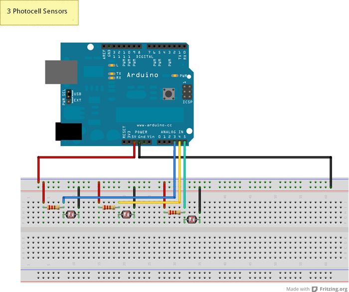
In this step we will be setting up three photocell sensors, all of these will be needed to complete the snake. Two of these sensors will become directional sensors, controlling the motors. The more light either the right or left sensor will have will control how much power each of the motors will receive, controlling the speed and direction of the snake’s movement. The last sensor will become the ambient light sensor, detecting how much light is in the room. This is necessary for each of the directional sensors so they can tell how much more light is being directed at them; and it is necessary for the leds, if the room is dark, the leds will light up.
Setting up the circuit
We used a similar setup as the instructable example for our photocell sensors. When getting one sensor, it is exactly the same. Just make sure the analog pins are placed in pins 2-5, as the motors will be using 0 and 1 (even though they are not plugged into them). We have used analog pins 3, 4, and 5. Where 3 and 4 are the directional sensors and 5 is the ambient sensor.
When setting up multiple sensors, just use the same circuit example as the first one. Each sensor must have its own line to power and ground and cannot be a part of the same circuit; this will make finishing the snake easier in future steps. Also, make sure your resistors are the same, since this affects the analog readings, we need all the sensors to be reading similar values.
Code
/*
int photocellReading3; // the analog reading from the analog resistor divider
int photocellReading4; // the analog reading from the analog resistor divider
int photocellReading5; // the analog reading from the analog resistor divider
void setup(void) {
Serial.begin(9600);
}
void loop(void) {
photocellReading3 = analogRead(3); // base light reading
Serial.print(“Analog reading 3 = “);
Serial.println(photocellReading3); // the raw analog reading
photocellReading4 = analogRead(4); // will go to motor 1
Serial.print(“Analog reading 4 = “);
Serial.println(photocellReading4); // the raw analog reading
photocellReading5 = analogRead(5); // will go to motor 2
Serial.print(“Analog reading 5 = “);
Serial.println(photocellReading5); // the raw analog reading
Serial.println(“”);
delay(1000);
}
*/
Again, the code is similar to the photocell instructable. We create photocell Reading variables to store the analog readings from the pins and then start the main loop. We will set the variable to the analog reading and print it out to see if it is working. We pause for 1 second, or else the reading will print out so fast we will be unable to read them.
Play around with sensors. Shine a flashlight into them to make the readings spike, cover them to make the readings drop. Your readings may have different values than ours, this is okay. Each sensor is different and it depends on the ambient light in the room at the time.
In the next step we will use these values to control the motors.
Step 3: Combine motors and photocell sensors
Description
In this step we will be taking the three photocell sensors and using them to drive the motor speeds. In our code we will be refering the motors to Motor A or Motor B, based on where they are plugged into the motor shield, and the sensors will be Sensor 3, Sensor 4, and Sensor 5, based on where they are attached to the analog readings. Sensor 3 and Sensor 4 will be the directional sensors and Sensor 5 will be the ambient light sensor.
Algorithm
To control the motors, we will be getting the base reading from all three sensors first (these are stored in photocellReading#).
We then take the differences between Sensor 3 and Sensor 5 (and store it in photocellDifference1) as well as the difference between Sensor 4 and Sensor 5 (and store it in photocellDifference2). This will tell us how much brighter the directional sensors are from the ambient sensor. Since the light will be shinning on these sensors, the difference readings should tell us how much light is being directed at each sensor.
We then subtract photocellDifference1 and photocellDifference2 from each other and store it in lrValue. By taking this difference, we are able to tell how much more light each directional sensor is sensing. If this number is negative than it means Sensor 4 has less light than Sensor 3 and more speed should be directed at Motor B. If the lrValue is positive than it means that Sensor 3 has more light than Sensor 4 and more speed should be directed to Motor A.
Code
/*
int photocellReading3; // the analog reading from the analog resistor divider
int photocellReading4; // the analog reading from the analog resistor divider
int photocellReading5; // the analog reading from the analog resistor divider
int photocellDifference1;
int photocellDifference2;
int lrValue;
void setup(void) {
Serial.begin(9600);
pinMode(12, OUTPUT); //Initiates Motor Channel A pin
pinMode(9, OUTPUT); //Initiates Brake Channel A pin
pinMode(13, OUTPUT); //Initiates Motor Channel B pin
pinMode(8, OUTPUT); //Initiates Brake Channel B pin
digitalWrite(13, LOW); //Establishes forward direction of Channel A
digitalWrite(8, LOW); //Disengage the Brake for Channel A
digitalWrite(12, LOW); //Establishes forward direction of Channel B
digitalWrite(9, LOW); //Disengage the Brake for Channel B
}
void loop(void) {
photocellReading3 = analogRead(3); // base light reading
photocellReading4 = analogRead(4); // base light reading
photocellReading5 = analogRead(5); // base light reading
//get differences between sensors for motors and ambient light sensor
photocellDifference1 = (photocellReading3 – photocellReading5);
photocellDifference2 = (photocellReading4 – photocellReading5);
// get difference between the two readings
lrValue = photocellDifference2 – photocellDifference1;
// control speed to each motor based on lrValue
if (lrValue <= -120 ) {
analogWrite(11, 255);
analogWrite(3, 100);
} else if (lrValue <= -90) {
analogWrite(11, 224);
analogWrite(3, 100);
}else if (lrValue <= -60) {
analogWrite(11, 193);
analogWrite(3, 100);
}else if (lrValue <= -40) {
analogWrite(11, 162);
analogWrite(3, 100);
}else if (lrValue <= -25) {
analogWrite(11, 131);
analogWrite(3, 100);
}else if (lrValue < 25) {
analogWrite(11, 100);
analogWrite(3, 100);
} else if (lrValue < 40) {
analogWrite(11, 100);
analogWrite(3, 131);
} else if (lrValue < 60) {
analogWrite(11, 100);
analogWrite(3, 162);
} else if (lrValue < 90) {
analogWrite(11, 100);
analogWrite(3, 193);
} else if (lrValue < 120) {
analogWrite(11, 100);
analogWrite(3, 224);
} else {
analogWrite(11, 100);
analogWrite(3, 255);
}
}
Video of the light sensors controlling the motors
Speed Break Down
In the code, you can see we have a long list of if else statements controlling the speed of each motor. This code works for our snake and our photocell sensor/motor combination. If you have changed the materials for your snake or find that these values don’t work for you, when feel free to change the values until you find speed control that works for you. Our snake is meant to work in low light and at a pretty fast speed. If you want your snake slower, for example, you may want to widen your range of lrValues in the if else statements, so that it will take a high powered light directed at one sensor before the motors reach highest speed.
For more detail: Build A Robot Snake Using Arduino