
Summary of Rainbow Jar – RGB Pixel Strip Controlled via Arduino
This article details the construction of a "Rainbow Jar," a popular Maker Faire display item featuring an addressable LED strip controlled by an Arduino. The project involves preparing the LED strip, creating a custom shield using pin headers and a stripboard to manage data and clock signals, and integrating an external 5V power supply via a jack connector for stability. The author provides step-by-step instructions on wiring colors, soldering techniques, and component placement to replicate the glowing jar effect.
Parts used in the Rainbow Jar:
- 50cm of Addressable LED Strip
- Plastic Sweetie Jar
- Arduino Uno
- Pin Headers
- Stripboard
- Rainbow Wire
- 5V Power Supply
- RGB LEDs (for light diffusion)
- 2.1mm female jack connector
Our most popular item on our display at Maker Faires is always the Rainbow Jar. One customer has already replicated it so we thought we’d share how we made it so you can make your own!
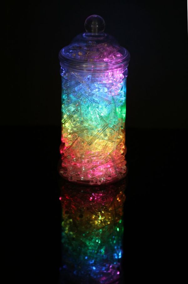
https://vine.co/v/hqxpVgdFQ9z (tried embedding this vine but it breaks instructables!)
Step 1: Getting Started – What you need
This is all the stuff we used.
What You’ll Need
50cm of Addressable LED Strip
Plastic Sweetie Jar (found them on eBay)
Arduino Uno
Pin Headers (UK)
Stripboard (UK)
Rainbow Wire
5V Power SupplySomething to diffuse the light – we’ve used RGB LEDs!
Soldering Iron and Solder
Wire Strippers
Craft Knife and Ruler
All of the links are to our site – in the US you can get everything from Adafuit orSparkfun
Step 2: Preparing the strip

The strip is controlled by an Arduino, using two control wires Data and Clock. We’re attaching green to the data and yellow to the clock. Orange to the +5V and Blue to the GND
Remove the red and brown wires from the rainbow cable and keep them for later. Strip the four wires at once using the super cool and handy Hakko Cutters.
If you’re using our Rainbow Cable then bend the orange and blue cables out a little. A little bit of solder added to the tips of the wire will help them adhere when you hold them onto the pads and add some heat from your soldering iron.
Step 3: Make a shield!
Now we make a little shield for the Arduino.
Take the pin headers and snap off two lots of four pins. Put them into the Arduino, you’ll want them in the 0,1,2,3 on one side and the Vin GND GND and 5V headers on the other side. Put the strip board on top and mark up how much of the board you need. They’re not opposite each other so you won’t need to do anything with the copper on the stripboard.
Score along the lines of what you need on the stripboard and snap it along the score lines.
Now we do a little alteration of the pin headers, pushing them down on a hard surface until the black plastic bit is flush with the hard surface. That way we can put the plastic bit on the side of the stripboard with no copper and have a nice bit to solder onto the copper.
Strip the other ends of the rainbow wire and solder the Clock and Data Pins to the strips that line up with 3 and 2 Respectively. Don’t worry if you do them the other way by mistake, you can change it in the code!
Solder the blue in line with one of the GND Pins and the orange in line with the 5V.
Step 4: Add External Power!
This seems to run fine as it’s only 50cm of strip through the Arduino, but lets make it a bit future proof adding external power, using a cool 2.1mm female jack.
Using a bit of the red and brown wire we cut earlier attach to the 5V and GND lines on the shield we just made. Attach the 5V to the +ve on jack connector and GND to the -ve.
For more detail: Rainbow Jar – RGB Pixel Strip Controlled via Arduino
- What components are required to build the Rainbow Jar?
You need a 50cm addressable LED strip, a plastic sweetie jar, an Arduino Uno, pin headers, stripboard, rainbow wire, a 5V power supply, and RGB LEDs for diffusion. - How do you connect the control wires to the LED strip?
Connect green to data, yellow to clock, orange to +5V, and blue to GND. - Can you change the code if Data and Clock pins are swapped?
Yes, the article states that if you accidentally swap them, you can simply change it in the code. - Why is an external power supply recommended for this project?
Although the strip runs fine through the Arduino, adding external power makes the setup future-proof. - What tool is suggested for stripping the four wires at once?
The article suggests using super cool and handy Hakko Cutters to strip the four wires simultaneously. - How should the pin headers be positioned on the Arduino?
Place two lots of four pins on headers 0,1,2,3 on one side and Vin GND GND 5V on the other side. - Which wire colors are removed from the rainbow cable initially?
The red and brown wires are removed from the rainbow cable and kept for later use with the power jack. - What is the purpose of bending the orange and blue cables out slightly?
Bending them helps them adhere when held onto the pads after adding a little solder to the tips.
