
Summary of Radioactivity detection using very simple ionization chamber and a single J-FET transistor
This article describes a simple, battery-free ionization chamber capable of detecting radioactivity from sources like smoke detectors. The device utilizes a multimeter's internal voltage to polarize electrodes within a copper-shielded enclosure, effectively filtering electromagnetic interference. A BF256B J-FET transistor serves as the core sensor element, converting ionization events into measurable resistance changes without an external power supply.
Parts used in the Simple Ionization Chamber:
- Copper plate
- BF256B n-channel J-FET transistor
- THT resistor (used for the gate electrode leg)
- Multimeter (Keysight 34460A)
- Tin foil
- Insulation tape
Today I will show a very simple ionization chamber that can detect radioactivity. I was able to detect with it ionizing radiation from a smoke detector (Am241 isotope). It’s also immune to electromagnetic interference (EMI) due to a good shielding.
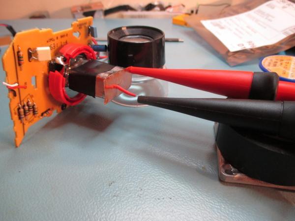
This device doesn’t explicitly use any power supply. It’s connected to a multimeter set to measure resistance, in this mode, the multimeter provides a small voltage to its probes (R=I/U, so to measure resistance, it has to put voltage across measured element). This is sufficient here, because basically we just need to polarise electrodes of the ionization chamber and nothing more. My multimeter provides 5.6V in this mode.
My setup is presented below, note that the sensor is this metal box, not the PCB visible on the image.
The chamber is made from copper plate soldered carefully to prevent any holes where electromagnetic fields could flow and disturb readings. Inside is one BF256B (n-channel J-FET) transistor, its gate is connected to one of ionization chamber plate made from a leg of a THT resistor, source pin is available externally, this is where “plus” probe of the DMM is connected, drain is connected to the metal case (that is both and electrode and is shielded against EMI).
I’ve used Keysight 34460A as a multimeter here, because it has histogram mode, that will be useful to look if the measured value is stable over time. PLC was set to 0.2, it will reduce accuracy, but will give much more samples.
Below two images present what is inside of the sensor (only JFET, as mentioned above) and the sensor mounted. The front was shielded using tin foil, that was secured tightly by insulation tape.
Read more: Radioactivity detection using very simple ionization chamber and a single J-FET transistor
-
How does the device detect radioactivity without a power supply?
The multimeter provides a small voltage across its probes in resistance mode to polarize the electrodes. -
What is the voltage provided by the multimeter for this setup?
The multimeter provides 5.6V in resistance measurement mode. -
How is electromagnetic interference prevented in this design?
It uses a copper plate soldered carefully to prevent holes and tin foil shielding secured with insulation tape. -
Which specific transistor is used inside the sensor?
A BF256B n-channel J-FET transistor is used. -
How are the transistor pins connected in the chamber?
The source pin connects to the DMM plus probe, the drain connects to the metal case, and the gate connects to a THT resistor leg. -
What function did the Keysight 34460A histogram mode serve?
It allowed the user to check if the measured value was stable over time. -
Why was the PLC set to 0.2 on the multimeter?
This setting reduced accuracy but provided many more samples for analysis. -
Can this device detect radiation from a smoke detector?
Yes, it was able to detect ionizing radiation from the Am241 isotope found in a smoke detector.
