PC sound cards form a readily available Signal Generator for testing electronic circuits. The utility of these signal generators is limited because the outputs are AC coupled and limited to ±2V.
Taking advantage of the two channels provided by the sound card this Instructable shows a scheme which uses one channel to output the Sin/Square/Triangle waveform with a fixed gain, while setting up a 441 Hz PWM square wave on the second channel. This PWM waveform is converted to ±8V averaged and summed with the first channel to provide a DC offset controllable by the duty-cycle setting.
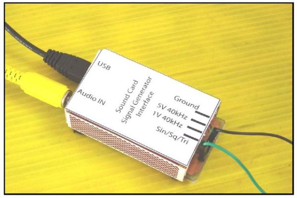
This PC sound-card interface implements a Signal-Generator with Sin/Square/Triangle output frequency variable from 50Hz to 10kHz, an amplitude variable from 0 to 5V and a variable DC offset of +/- 4V.
As a bonus the MAX232 , SMD/DIP, provides a 40kHz / 100kHz signal which can be used for step-response testing of analog circuits.
How I went about it:
1. Scribbled the Idea on to a piece of paper.
2. Selected the devices required and drew the prototype circuit.
3. Bread-Boarded the circuit and developed the PC GUI software.
4. Decided to do a professional job.
5. Obtained free samples from Texas Instruments. ( This is a great facility provided by TI)
6. Drew the Schematic and Designed the PCB using Eagle 5.10.0
7. Fabricated the double-sided SMD PCB using the toner-transfer method. ( It is possible to handle these fine pitch devices)
8. Populated the PCB and checked out the functioning.
9. Made minor changes in the GUI software to handle Channel-Interchange and Offset-Invert.
10. Put the circuit into a small-matchbox enclosure.
11. Wrote up the documentation for this system.
12. Archived all technical data in a .rar file
For more detail: PC Sound-Card Signal-Generator-Interface