Summary of Pan/Tilt Motion System for Control Education
This article describes a Pan/Tilt Motion System designed for control education, featuring a rotating base and an elevation arm. The system uses two servo motors to control azimuth (base) and zenith (arm) angles. An Arduino board acts as the interface, receiving real-time input from a Simulink controller to drive the motors. The project includes detailed sections on building, installation, parameter identification, and experimental tracking.
Parts used in the Pan/Tilt Motion System:
- Rotating base
- Elevation arm
- Drive train
- Servo motor (for base propulsion)
- Servo motor (for altitude propulsion)
- Arduino control board
- Simulink controller
- Stepper motors (controlling zenith and azimuth angles)
Pan/Tilt Motion System for Control Education
Ricardo G. Sanfelice, University of Arizona
Project supported by Mathworks
Website developed by Colin Lasharr, University of Arizona
Contents
- Introduction
- Instructions for Building the System
- Installation Instructions
- The Arduino Board
- Simulink
- Initial Parameter Identification
- System Identification for Zenith Component
- System Identification for Azimuth Component
- Running An Experiment
- Tracking and Error Data
- Resources
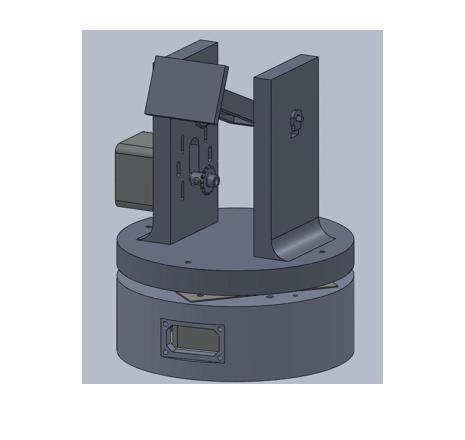
Introduction
The device is composed of a rotating base with an elevation arm to orient the attitude of energy collectors, which are modular. The base of the device is linked to a drive train that is powered by a small servo motor and provides the propulsion to orient the attitude of the device. The elevation arm is connected to another small servo motor which provides the propulsion to orient the altitude of the device.
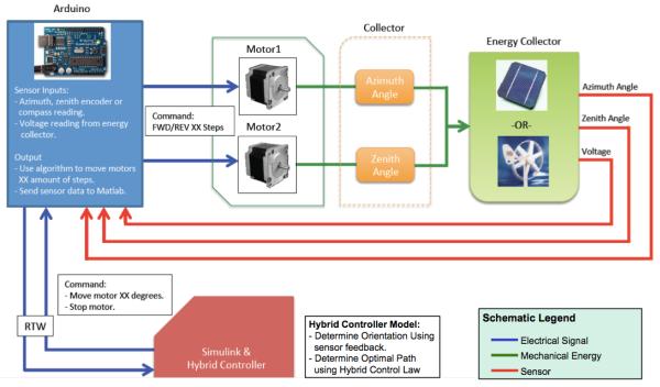
The system is composed of an Arduino control board that receives input from the Simulink controller in real time, and then sends output to the motors. There are two stepper motors which control the zenith and the azimuth angles. These motors position the base and arm of the device.
For more detail: Pan/Tilt Motion System for Control Education
- What is the primary purpose of this device?
The device is designed for control education and orients the attitude of modular energy collectors. - How are the base and arm moved?
A small servo motor powers the drive train for the base, while another small servo motor controls the elevation arm. - Which board receives input from the controller?
The Arduino control board receives input from the Simulink controller in real time. - What components position the base and arm?
Two stepper motors control the zenith and azimuth angles to position the base and arm of the device. - Can the system be built according to instructions?
Yes, the article provides specific instructions for building the system. - Does the system support parameter identification?
Yes, the article covers initial parameter identification and system identification for both zenith and azimuth components. - What data can be tracked during an experiment?
Users can track and view error data while running experiments with the system.