Introduction
It’s been so long since I had the idea for this project that I can’t remember why I had the idea in the first place. At least I blame it on the passage of time although this engineer is getting on a bit now so it could easily be memory rot on my part. So here we are then, a reflow oven controller. Let’s quickly recap what a reflow oven is for those that are new around here.
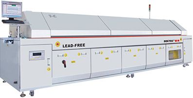
The two main processes used in industry to build printed circuit boards are wave soldering and reflow using a very large industrial oven that you probably can’t afford and if you could afford to buy it you probably couldn’t afford to house or run it.
Reflow on the large scale is achieved by applying solder paste to the printed circuit board using a laser-cut stencil with cutouts placed precisely where the pads are located. The solder paste itself is a mixture of flux and tiny balls of solder. A pick-and-place machine lifts the components from their packaging, e.g. a tape and reel dispenser and places them on to the board with their pads resting in the little gobs of solder paste.
The board then gets placed into the oven where a carefully controlled temperature profile is applied over the course of about 5 minutes. During this time the solder paste melts and the components ‘sit down’ into place before the solder sets as the board cools.
We can apply this basic technique to the hobbyist world with a simple plan of action. The pick-and-place machine will be replaced by my right arm and a pair of tweezers. A cost of zero so far, great stuff. Stencils and solder paste are both available to the hobbyist but the cost of the stencils are relatively high if you’re going to be making only a few boards and the solder paste needs refrigerated storage and only has a short shelf life. I’ll replace this part with a simple tinning of my boards using a soldering iron. It’ll take longer but should work just as well.
Finally we have the oven itself. Small ovens in various forms are available on ebay, amazon and they might even sell them in real shops made out of real bricks and staffed by real people. The fun part of the question is how do we make our oven follow a pre-programmed temperature profile instead of just powering up to a target temperature and staying there until the dinger goes ding and your chicken is roasted.
Of course we’re going to use a microcontroller to do it and that’s what the bulk of this article is about. Please read on.
Prior art
I’m not the first to build an MCU-based reflow oven controller and I’m probably not going to be the last. A quick google around throws up the following results, and these are just the guys that have put virtual pen to paper and taken the time to publish their work.
- Here’s an Arduino shield-based controller that looks professionally produced and generally well thought out.
- Dan Strother’s effort is a simple affair but his firmware is very good. While you’re there take a look at his Spartan-6 BGA test board. I can’t believe he did it with Eagle, there’s only so much pain a man can take.
- Sparkfun did one once and then pulled it. Goodness knows why.
- There’s even an instructable that you can follow.
There’s more. There’s a lot more, so why another one? The commercially available controllers didn’t look particularly inspiring to me so a self-build was going to be the way to go. I could either follow someone else’s schematic or come up with my own. Well I felt up to the challenge of doing it myself and bringing my own bit of flair to the presentation as well as making it highly cost-effective.
Component selection
A significant number of components need to come together harmoniously for this project to work. In this section I’ll go over the main component parts and how I selected them.
The Solid State Relay
A solid state relay (SSR) is designed to allow you to switch mains voltages on and off using low voltage DC control, i.e. a microcontroller. They do this by using an optocoupler to internally isolate the two sides from each other. When you trigger the photodiode the mains current is allowed to flow. However, it’s not quite as simple as that. The relay will only change the state of the AC output at the two points in the AC sine wave where it crosses zero so that the input and output waveforms are maintained, the zero-crossing. That imposes limits on the frequency we can use to switch it on and off, something which I will tackle in the firmware design.
The best quality SSRs are made in the USA and you do get what you pay for. There are cheap Chinese Fotek SSRs on ebay for a fraction of the cost of the USA-made SSRs. I knew I was going to need a heatsink so I got one on ebay that came with one of the Fotek’s attached. They were so cheap that I thought I’d get one just to see what they were like.
I tested the Fotek using a light load — literally — it was a desk lamp and it did what it was supposed to do, no problems there. Reports on the internet from users of the Fotek range from ‘it caught fire’ to ‘I’ve been using it for years with no problem’. I suspect that some users don’t realise that you must cool an SSR. It probably doesn’t help that the Fotek only comes with a little aluminium plate on the base that does not shout out its role as a heatsink.
I unscrewed the base to take a look at the innards but could only get it out a few millimetres without damaging the internal wiring. From what I could see there is a PCB housed towards the top of the unit and then a set of bare wires come down to the aluminium base plate where an unidentifiable component is soldered directly to it. This must be the heat generating component.
The overall cheapness of the Fotek did not fill me with confidence so I loitered some more on ebay and managed to pick up a brand new USA-made device for about £8.
The difference in quality is immediately obvious. This device is completely solid and resin-filled. It feels like a proper industrial component and a stamp on the side declares that it’s ’200% tested’. My only reservation is that the AC and DC terminals are only air-gapped. The Fotek, for all its faults, physically separates the two sides so arcing or shorting from the AC to the DC would be practically impossible.
Just look at that base plate. If you were ever in any doubt that this is a device designed to be attached to a heatsink then you won’t be after you see that. I unscrewed the Fotek from its heatsink, applied some thermal transfer gunk that I had left over from a computer HSF kit and screwed in the Opto-22 device. I’m now confident that there won’t be any smoke coming from my mains control unit.
The temperature sensor
After doing some research it turns out that the most popular IC for handling the amplification and analog to digital conversion of the thermcouple readout is the MAX6675 and its successor, the MAX31855 from Maxim. The two devices have the same footprint and pinout but are not software compatible and may not all work with the same thermocouples.
The MAX6675 can read a range of 0 to 1023°C with 0.25°C resolution. The MAX31855 extends the capabilities by being able to read below zero but it adds the limitation that the thermocouple must not be grounded. The MAX6675 can be grounded and in fact it must be grounded if you want to take advantage of its ability to sense an open (disconnected) state. I decided to design the board to be able to handle either type of sensor IC using a jumper to ground it and I’ll be using the MAX6675 on my own build.
A defective MAX6675
The MAX6675 (and its successor, the MAX31855) are rather expensive little chips but I noticed that they were available on ebay for just a few pounds so I bought one. Mistake. I wasted about half a day trying to figure out why the readings I was getting from it were scaled up by a factor of 8. It just didn’t make any sense.
I couldn’t just say, yeah whatever and write my software to scale down by 8 because the maximum reading would be 128°C which is way too low for a reflow oven. This issue had to be resolved.
Eventually I decided to try removing it from the board and replacing it with one that I got from a different seller on ebay that had slightly different numbering printed on the case, perhaps indicating a different batch. It worked perfectly. Lesson learned, it’s just not safe to buy ICs on ebay because you don’t know where they’re sourced from. Next time I’ll swallow the cost and stick to the usual major name suppliers that I usually use.
Anyway, in case it helps anyone else here’s a picture of the bad IC. If you’ve got one with the same ‘+120′ numbering and it’s misbehaving then drop-kick it into the waste bin and replace it with one from a reputable supplier.
For more detail: An open-source Cortex-M0 halogen reflow oven controller with TFT LCD