Summary of Multiplexing with Arduino and the 74HC595
This tutorial demonstrates how to drive a 4x4 LED matrix using an Arduino Uno and a single 74HC595 shift register via multiplexing. This technique allows all 16 LEDs to be controlled using only three digital pins by rapidly switching rows, leveraging persistence of vision. The guide covers the principles of multiplexing, the operation of the 74HC595 chip, wiring schematics, and physical assembly steps for both Sparkfun PCBs and custom breadboard builds.
Parts used in the 4x4 LED Matrix Project:
- Button Pad 4x4 - LED Compatible Sparkfun COM-07835
- Button Pad 4x4 - Breakout PCB Sparkfun COM-08033
- Arduino Uno Sparkfun DEV-11021
- White 5mm LED (Digikey C513A-WSN-CV0Y0151-ND)
- 74HC595 shift register (Digikey 296-1600-5-ND)
- 16 pin IC socket (Digikey A100206-ND)
- 16 conductor ribbon cable (Jameco 28RC16-10VP)
- 16 pin right angle connector (Jameco 746285-3)
- Male header pins (Jameco 7000-1X40SG-R)
- 22 Gauge Wire
- Protoboard with copper
- Solder and wire cutters/strippers
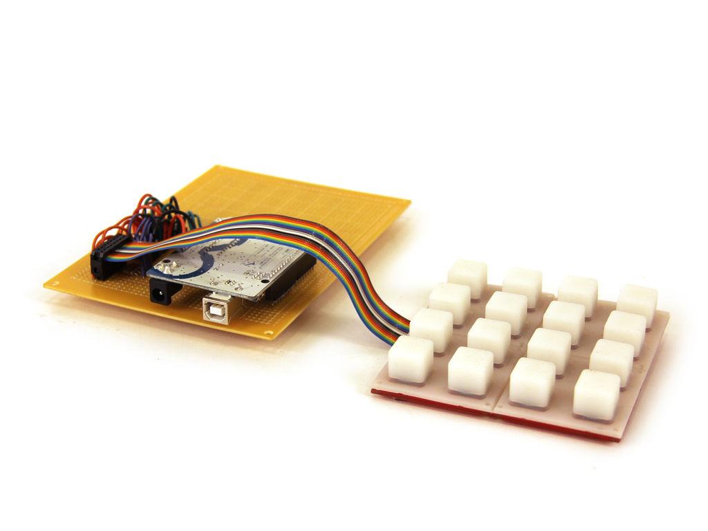
The finished product will look like this:
I used the sparkfun button pad pcb to build my 4×4 led matrix because this is the first step in a longer project I’m working on that involves backlit buttons. However, you can build your own 4×4 led matrix pretty easily on a breadboard, and I’ll provide schematics that will show how to do that. My parts list is given below:
Parts List:
SPARKFUN:
(1x) Button Pad 4×4 – LED Compatible Sparkfun COM-07835
(1x) Button Pad 4×4 – Breakout PCB Sparkfun COM-08033
(1x) Arduino Uno Sparkfun DEV-11021
DIGIKEY (you could find these at Jameco):
(16x) White 5mm LED (3mm is fine too) Digikey C513A-WSN-CV0Y0151-ND
(1x) 74HC595 shift register Digikey 296-1600-5-ND
(1x) 16 pin IC socket Digikey A100206-ND
JAMECO:
(1x) 16 conductor ribbon cable Jameco 28RC16-10VP
(1x) 16 pin right angle connector Jameco 746285-3
(2x) male header pins Jameco 7000-1X40SG-R
Additional Materials:
22 Gauge Wire, multiple colors Radioshack #278-1221
protoboard with copper Radioshack #276-147
wire cutters
wire strippers
solder
Step 1: What Is Multiplexing?
In a multiplexed array of LEDs, only one row of LEDs is on at any given time. It seems like this would limit the types of shapes we can display on the LED matrix, but it actually doesn’t. This is because the arduino (or whatever is sending data to the array) is switching through each row so quickly (hundreds or thousands of times a second) that we do not perceive the flashing on and off of each consecutive row. You can read more about this phenomenon, called persistence of vision, on wikipedia.
So how do we send data to one row at a time? If we connect five volts (red) to one row and connect ground (blue) to the other three rows and cycle through each row one by one, it will look something like figure 1. Now image that while one of the rows is at +5, we connect one of the columns to ground. As shown in figure 2, this will cause the LED at the junction of the +5 row and GND column to light up. This way, we can address each of the 16 LEDs in the matrix individually using only eight leads (four to the rows and four to the columns).
Now look at the image below. Imagine if we very quickly turn on the LED in the upper left corner (position 1,1), then the LED at (2,2), then (3,3) and (4,4), and we cycle between these four LEDs very quickly (hundreds of times a second). It will appear that all four of these LEDs are on a the same time (as shown in right image in the image below). Study the diagram below and convince yourself that this is true.
Step 2: How does the 74HC595 work?
The 74HC595 is controlled by three connections to the arduino (or your microcontroller of choice); they are called the data pin, latch pin, and clock pin. Refer to the flow diagram above (figure 1):
-first the latch pin is set to ground to disable the outputs, this way the output pins won’t change as we are sending in new data to the 74HC595
-next new data is sent to the 74HC595 serially, by pulsing the clock pin and sending each byte of new data out the data pin bit by bit. Arduino has a handy function in their library called shiftOut that takes care of this for you.
-finally, set the latch pin high. This sends your new data to all the output pins at once (parallel output).
In this tutorial I’ll show you how to control a 4×4 LED matrix with one 74HC595. In the previous step I showed that it is possible to control a 4×4 LED matrix using only 8 pins (four for the rows and four for the columns). In the next steps I’ll show you how to wire the 4×4 LED matrix to the 8 output pins of the 74HC595 and drive the entire thing with the arduino.
One more thing to add about the 74HC595:
It is also possible to expand your outputs even further by daisy chaining 74HC595, but that is outside the scope of this tutorial.
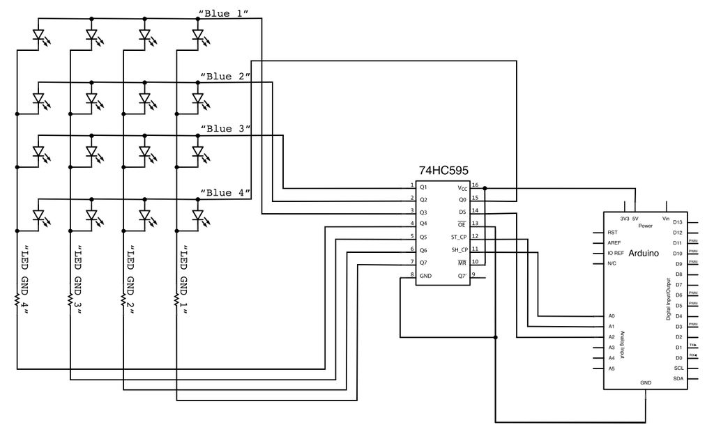
Step 3: Schematic
Arduino Pin Connections to 74HC595
A0 Clock Pin (pin 11)
A1 Latch Pin (pin 12)
A2 Data Pin (pin 14)
Step 4: Solder LEDs to Sparkfun PCB
Thread the leads of 16 LEDs (5mm or 3mm are fine, I used 5mm) through LED holes in the sparkfun PCB. These boards are compatible with 4 lead RGB LEDs, so there are four available holes on each button pad. You can use the two center holes for single color LEDs (see figure 3). Be sure that the flat edge of the LED (the cathode) lines up with the flat marking on the PCB.
Solder the LED leads and cut away the excess wire.
If you do not have a sparkfun PCB:
See figures 7 and 8 for the LED matrix wiring diagram. Connect the anodes (long lead) of each row of LEDs together and the cathodes (shorter leads) of each column of LEDs together in the matrix.
For more detail: Multiplexing with Arduino and the 74HC595
- How many digital pins does the finished product require?
All 16 LEDs will require only three of the Arduino's available digital pins. - What is the cost of a 74HC595 chip?
The chip costs about 60 cents apiece. - Can I build the matrix on a breadboard instead of using the Sparkfun PCB?
Yes, you can build your own 4x4 led matrix pretty easily on a breadboard. - How fast must the arduino switch through each row?
The arduino switches through each row hundreds or thousands of times a second. - What phenomenon prevents us from perceiving the flashing rows?
This is called persistence of vision. - Does the 74HC595 have inputs or outputs?
The 74HC595 has 8 outputs labeled Qa-Qh and cannot read data from these pins. - Which function in the Arduino library handles serial data sending?
Arduino has a handy function called shiftOut that takes care of this for you. - How do we address individual LEDs in the matrix using leads?
We can address each of the 16 LEDs individually using only eight leads. - What happens when the latch pin is set high?
Setting the latch pin high sends the new data to all the output pins at once. - Can the 74HC595 read analog data from sensors?
No, it should not be used to read analog data from sensors or potentiometers.