Summary of Mini CNC Laser Wood Engraver and Laser Paper Cutter.
This project describes building a 40 x 40 mm laser CNC wood engraver and thin paper cutter using recycled DVD drive mechanisms, an Arduino Nano, A4988 drivers, and a 250 mW focusable laser. The author salvaged parts, measured stepper screw lead to calculate resolution, built acrylic frames and sliding rails, wired steppers and electronics, configured microstepping (1/16), and mounted the laser with simple hardware. Laser safety glasses and proper power regulation (LM7805) are emphasized.
Parts used in the Mini CNC Laser Wood Engraver and Laser Paper Cutter:
- Arduino Nano (with USB cable)
- 2x DVD drive stepper mechanisms (including stepper motors, lead screws, sliders)
- 2x A4988 stepper motor driver modules (or GRBL shield)
- 250mW focusable laser module (650nm)
- 12V 2A power supply (minimum)
- IRFZ44N N-CHANNEL MOSFET
- 10k resistor
- 47 ohm resistor
- LM7805 voltage regulator with heatsink
- Blank PCB board (20mm x 80mm)
- Male and female header pins
- 2.5mm JST XH-Style 2-pin male connector
- 1000uF 16V capacitor
- Jumper cables
- 8x small neodymium magnets (from DVD lens mechanism)
- 2-pin plug in screw terminal block connector
- Zip ties (100mm)
- Super glue
- Epoxy glue
- Wooden plyboard
- Acrylic sheet
- Some M4 screws, bolts and nuts
- Laser safety glasses
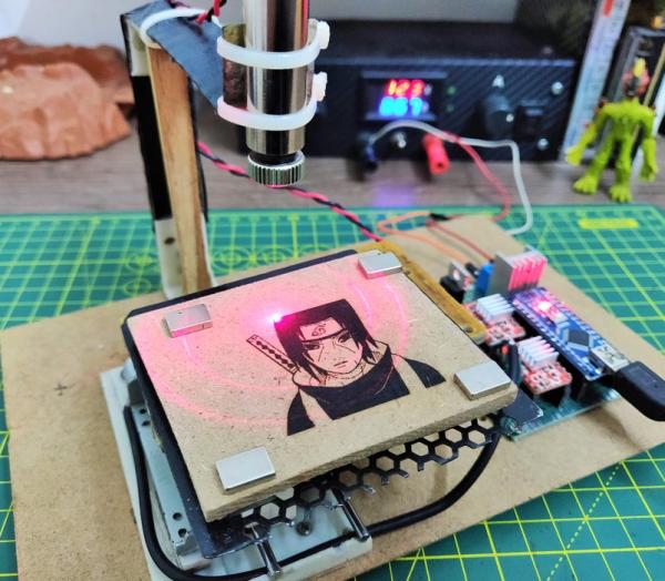
This is an Instructables on how I made an Arduino based Laser CNC wood engraver and Thin paper cutter using old DVD drives, 250mW laser. Playing area is 40mm x 40mm max.
Isn’t it fun making a own machine out of old things?
Step 1: Parts and Materials Required
- Arduino Nano (with usb cable)
- 2x DVD drive stepper mechanism
- 2x A4988 stepper motor driver modules (or GRBL shield)
- 250mW Laser with adjustable lens (or above)
- 12v 2Amps power supply minimum
- 1x IRFZ44N N-CHANNEL Mosfet
- 1x 10k resistor
- 1x 47ohm resistor
- 1x LM7805 voltage regulator (with heatsink)
- Blank PCB Board
- Male and Female Headers
- 2.5mm JST XH-Style 2pin male connector
- 1x 1000uf 16v capacitor
- Jumper cables
- 8x small neodymium magnets ( which I have salvaged from DVD lens mechanism)
- 1x 2pin plug in screw terminal block connector
- Zip ties (100mm)
- Super Glue
- Epoxy Glue
- Wooden plyboard
- Acrylic sheet
- Some M4 screws, bolts and nuts
- Laser Safety Glasses
LASER SAFETY GLASSES are must needed in this project.
Most of all the parts salvaged or are brought from China through a site called BANGGOOD.
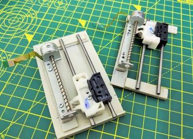
Step 2: Taking Apart the DVD Drive Stepper Mechnaism
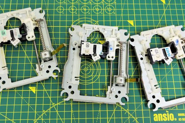
Two DVD driver mechanism are required, one for the X-Axis and the second for the Y-axis.
Using a small Phillips head screw driver I removed all the screws and detached stepper motor, the sliding rails and the follower.
The stepper motors are 4-pin Bipolar Stepper Motor.
The small size and low cost of a DVD motor mean that you can’t expect high resolution from the motor. That is provided by the lead screw.
Also, not all such motors do 20 steps/rev. 24 is also a common spec. You’ll just have to test your motor to see what it does.
Procedure for calculating the resolution of the CD Drive Stepper motor:
In order to measure the resolution of the CD/DVD drive stepper motor, a digital micrometer was used. The distance along the screw was measured. The total length of the screw using a micrometer, which turned out to be 51.56 mm. To determine the lead value which is the distance between two adjacent threads on the screw. The threads were counted to be 12 threads within this distance. Lead = distance between adjacent threads = ( total length / number of threads = 51.56 mm) / 12 = 4.29mm/rev.
The step angle is 18 degrees which corresponds to 20 steps/revolution. Now that all the information needed is available, the resolution of the stepper motor could be calculated as shown below:
Resolution = (Distance between adjacent threads) / (N Steps/rev) = (4.29mm/rev) / (20 steps/rev) = 0.214 mm/step. Which is 3 times better the resolution required which is 0.68mm/step.
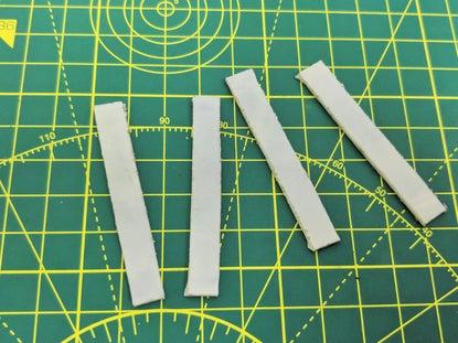
Step 3: Assembling the Slider Rails for the X and Y-Axis
For the sliding rails I’ve used 2 extra rods for the better and smooth performance. The main function of the slider is to slide on rod freely with minimal friction between the rod and the slider.
It took me some time to make the slider glide freely on the rod.
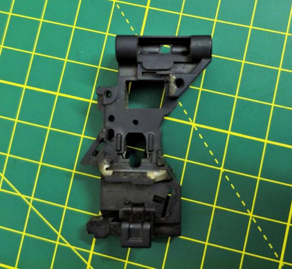
Step 4: The Main Frame for the Stepper X and Y
Using some Acrylic sheets I had made two of the main frame for the stepper and the sliding rails. The stepper motor has spacers between the main frame and its base, and it is necessary for the Axis.
Step 5: Attaching the Sliding Rail With the Main Frame
First using super glue I’ve tried adjusting the proper position of the rails, where they should be so that the follower makes proper contact with the stepper thread. The contact should be proper not too tight or not too slag. If the contact is not proper between the follower and the thread, steps will skip or motor will draw more current than usual in running condition. It takes some time in adjusting.
Once its was adjusted, using Epoxy glue I fixed them.
Step 6: Wiring of Stepper Motors
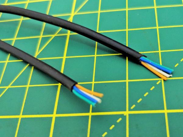
For the stepper motors I’ve used old usb cable, because it has 4 wire inside and have a cover on it, and it is more flexible and easy to work with.
Using continuity mode in Multimeter determine determine 2 Coil, Coil A and Coil B.
I made 2pairs of wire by selecting colours, one pair for the Coil A and second for the Coil B. Soldered them and used heat shrink tube on it.
Step 7: Combing the X and Y Axis
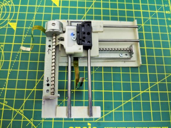
X and Y co-ordinates movement.
I’ve attached the slider of X and Y-axis together in perpendicular to each other, using some spacer between them. And also attached a thin metal grill above it as a working bed. Neodymium magnets are used as work piece holder.
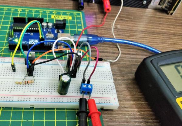
Step 8: The Electronics
PARTS USED FOR THE DRIVER ARE:
- Arduino Nano.
- 2x A4988 Stepper motor drivers.
- 1x IRFZ44N N-CHANNEL MOSFET.
- 1x LM7805 Voltage regulator with Heatsink.
- 1x 47ohm and 1x 10k resistor.
- 1x 1000uf 16V capacitor.
- 1x 2.5mm JST XH-Style 2pin male connector.
- MALE and FEMALE Header Pins.
- 1x (20mm x 80mm blank PCB).
In GRBL the digital and analog Pins of Arduino are reserved. The ‘Step’ pin for the X and Y axes is attached to digital pins 2,and 3 respectively. The ‘Dir’ pin for the X and Y axes is attached to digital pins 5 and 6 respectively. D11 is for laser Enable.
The Arduino gets power through the USB Cable. The A4988 Drivers through external power source. All ground share common connections. VDD of A4988 are connected to 5V of Arduino.
The laser I’ve used runs on 5V and has built in constant current circuit. For the constant 5V source from the external power supply LM7805 voltage regulator is used. Heatsink is compulsory.
The IRFZ44N N-CHANNEL MOSFET works as an elelctronic switch when receives digital high signal from pin D11 of Arduino.
NOTE: 5V from Arduino nano can’t be used beause the laser draws more than 250mA and the Arduino Nano is not capable of delivering that much of current.
Configuring Micro Stepping for Each Axis.
MS0 MS1 MS2 Microstep Resolution.
Low Low Low Full step.
High Low Low Half step.
Low High Low Quarter step.
High High Low Eighth step.
High High High Sixteenth step .
The 3 pins (MS1, MS2 and MS3) are for selecting one of the five step resolutions according to the above truth table. These pins have internal pull-down resistors so if we leave them disconnected, the board will operate in full step mode. I’ve used the 16th step configuration for smooth and noise free. Most (but certainly not all) stepper motors do 200 full steps per revolution. By appropriately managing the current in the coils it is possible to make the motor move in smaller steps. The Pololu A4988 can make the motor move in 1/16th steps – or 3,200 steps per revolution.The main advantage of microstepping is to reduce the roughness of the motion. The only fully accurate positions are the full-step positions. The motor will not be able to hold a stationary position at one of the intermediate positions with the same position accuracy or with the same holding torque as at the full step positions.Generally speaking when high speeds are required full steps should be used.
Step 10: Laser Assembly
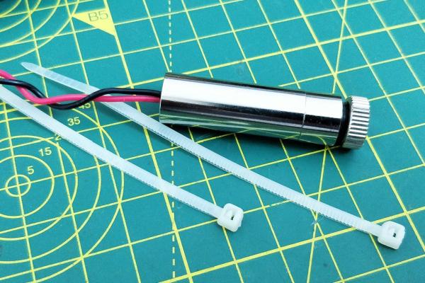
The laser I’ve used is Focusable Laser Module 200-250mW 650nm. The outer metal housing work as a Heatsink for the laser diode. It has focusable lens for the adjustment of laser dot.
Using two Zip-ties I’ve mounted the laser with the stand. Heatsink for laser also can be used, but my laser wasn’t overheating so I din’t used it. Connect the laser wire terminal to the laser socket on the driver board.
Source: Mini CNC Laser Wood Engraver and Laser Paper Cutter.
- What components are required to build this laser CNC?
The article lists Arduino Nano, 2 DVD drive stepper mechanisms, 2 A4988 drivers, 250mW laser, 12V power supply, IRFZ44N MOSFET, LM7805 regulator, resistors, capacitor, PCB, headers, connectors, magnets, zip ties, adhesives, acrylic, screws, and safety glasses. - How many DVD drive mechanisms are needed?
Two DVD drive mechanisms are required: one for the X axis and one for the Y axis. - How is the stepper motor resolution calculated?
Resolution is calculated by measuring screw lead (distance between adjacent threads) and dividing by steps per revolution; example given: 4.29 mm/rev divided by 20 steps/rev = 0.214 mm/step. - Can the Arduino 5V pin power the laser directly?
No, the article states the Arduino 5V cannot be used because the laser draws more than 250 mA; an LM7805 from external supply is used. - Which Arduino pins are used for step and direction?
The article assigns Step pins to digital pins 2 and 3, Direction pins to digital pins 5 and 6, and D11 for laser enable. - How is microstepping configured on the A4988?
Microstepping uses MS0, MS1, MS2 pins with states defined in the table; the author uses 1/16 step (MS0 High, MS1 High, MS2 High) for smooth operation. - What is used to hold workpieces on the bed?
Small neodymium magnets salvaged from the DVD lens mechanism are used as workpiece holders on a thin metal grill bed. - How is the laser mounted?
The laser module is mounted using two zip ties on a stand; its metal housing serves as a heatsink and it has a focusable lens. - Is a heatsink required for the laser or regulator?
The LM7805 requires a heatsink; the laser housing acts as a heatsink and the author did not add an extra heatsink because it did not overheat. - What safety equipment is emphasized?
Laser safety glasses are emphasized as must have for this project.