
Summary of Mini 7-Segment Clock V3
The article details the enclosure design process for the Mini 7-Segment Clock v3, utilizing a 3D model created in SketchUp from an EAGLE PCB export. The designer opted for a minimal, open-frame approach to showcase the electronics rather than hiding them in a project box. Key innovations include internal raised rails for securing the PCB without mounting holes and a decision to use pogo pins instead of soldering an ICSP header to avoid interference with the power cord.
Parts used in the Mini 7-Segment Clock v3 Enclosure:
- Mini 7-Segment Clock v3 PCB
- EAGLE software (for PCB export)
- SketchUp (for 3D modeling)
- 3D-printed enclosure frame
- Raised rails (internal divider components)
- Pogo pins (for programming)
- Acrylic back panel
- Power cord
While I waited for the Mini 7-Segment Clock v3 PCBs to arrive, I got to work on designing an enclosure. First, I exported the PCB from EAGLE to SketchUp.
I then assembled a complete 3D model with all the necessary components.
With the 3D model complete, I could then design an enclosure to house the PCB and know exactly what it’s going to look like before printing it. I even incorporated a little cable strain relief.
There are no mounting holes on the PCB, so I can’t use board stands. I had to think of an ingenious way to secure the PCB into the enclosure, keeping both sides of the PCB visible, with a model that I can actually print
The solution was to incorporate some little raised rails along the inside of the enclosure. The PCB will be held in place by snapping it into the 3D-printed frame between the inner-divider and those rails.
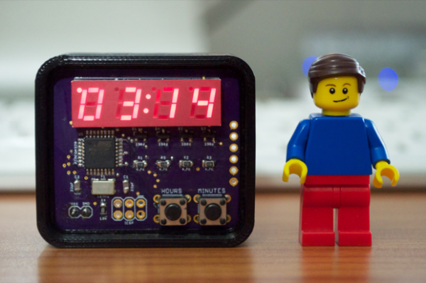
The design is very minimal, it’s just enough to keep the clock upright. I think it’s going to look pretty sweet. I don’t want to hide the PCB in a little project box where all you can see is the display. I want to showcase the PCB and the electronics.
The PCB has a 6-pin ICSP header for burning the bootloader, but I’m not going to solder in a header. I’ve always wanted to try and program a chip with pogo pins. What’s the use of soldering in a header if it’s only going to be used once? Seems like a waste. Not to mention, sometimes it just gets in the way. The ICSP header on version 2 of the Mini 7-Segment Clock got in the way of the power cord. It wasn’t apparent until I screwed on the back panel and realized what little space I had to work with. I managed to squeeze the cable through the hole in the acrylic, but it was tight.
For More Details: Mini 7-Segment Clock V3
-
How was the 3D model created?
The PCB was exported from EAGLE to SketchUp to assemble a complete 3D model before designing the enclosure. -
Why were board stands not used?
Board stands could not be used because there are no mounting holes on the PCB. -
How is the PCB secured inside the enclosure?
The PCB is held in place by snapping it into the 3D-printed frame between the inner-divider and raised rails. -
What is the reason for using pogo pins instead of a header?
Pogo pins are used because soldering a header is considered a waste if only used once for burning the bootloader and can get in the way. -
Did previous versions have space issues with the power cord?
Yes, the ICSP header on version 2 got in the way of the power cord until the cable was squeezed through the acrylic hole. -
What is the design philosophy for this enclosure?
The design is minimal to keep the clock upright while showcasing the PCB and electronics rather than hiding them in a project box.
