If you are like me, there are many nostalgic things that bring me back to my youth.
Tom Sutton, username yakis on thingiverse, created this 3d model of Metroid’s Samus in morph ball form.
It has room inside for LEDs to light it up. I have enhanced mine with a vibration sensor, neo pixel lights so the colors can change, and a tiny computer. This makes it possible to have multiple modes you can cycle through and with pulsing lights you can trigger with a tap.
I think you’ll agree, it makes one really engaging prop. I’ll show you how to make one in this video.
Supplies
I get a commission on purchases made through some of these links:
https://www.adafruit.com/product/1612 NeoPixel PCB https://www.adafruit.com/product/2384 Vibration Sensor https://www.adafruit.com/product/2750 350mAh LiPo battery https://www.adafruit.com/product/3500 Trinket M0 5v https://www.adafruit.com/product/1863 Switched JST board
https://amzn.to/2JQOfg3 Rare earth magnets
https://amzn.to/38o68wQ Transparent PETG filament
https://amzn.to/3n6AGre Copper Silk PLA filament
https://amzn.to/2IjC62c Gray PLA filament
https://amzn.to/38jWBqG Mini bread board
https://amzn.to/3pa2WLk heat shrink insulation tubing
Step 1: Prepare Parts
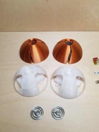
3D printed model parts. I use this incredible Copper Silk PLA (128
grams), 3 grams Grey PLA, and Transparent PETG (74 grams)
https://www.thingiverse.com/thing:2785965
Download and print the STL files from Thingiverse
For the computer I went with the Trinket M0 5v from Adafruit. This little guy is more than powerful enough for this project and is the perfect size to fit inside the ball.
We also need 6 neo pixels. These come assembled on a PCB making it easier to solder them in to a flexible chain to go in the morph ball.
Pic neo pixels
Now to open up more possibilities, I added a vibration sensor. This is the medium sensitivity sensor from Adafruit. This are crazy simple devices with a coiled wire around a straight wire sitting inside the coil. When you bump the sensor, the wires make momentary contact with each other that we can detect.
For the battery I am going a 150mAh battery which from use seems to be able to provide a charge for at least 45 minutes
To make it easy to switch on and off the power I used this switched JST break out board.
To keep the 2 halves of the ball together we need 6 x 8mm Rare earth magnets.
And this mini bread board is a nice size to fit in the small space we have in the ball.
And lastly we need some code for the computer. I have a good starter program that you can use as it is or modify with your own new modes.
https://github.com/vincestechshop/morph-ball
Step 2: Assemble the Electronics
Dremel the tabs off of the mini bread board so it can fit
Solder 2 header pins to the vibration sensor and bend them about 110 degrees (see pic of all assembled electronics)
Solder the neopixels into a chain with lengths 15cm, 7cm, 7cm, 17cm, 7cm, 7cm. The 15cm length should have 3 header pins soldered on them to make it easy to insert in to the bread board.
Solder the header pins to the JST board
Solder the header pins to the trinket board
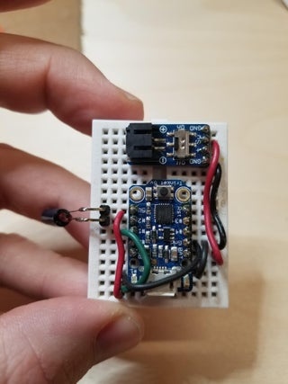
Connect parts on the breadboard as shown in the picture
Step 3: Load the Software and Test
It is important to load the software at this point and test that everything is working before securing anything to the sphere halves.
Download the starter code from https://github.com/vincestechshop/morph-ball
And load it on the trinket with the Arduino IDE.
Verify that all of the neopixels light up and that you can trigger a mode change by bumping the sensor.
Step 4: Assemble the Rest
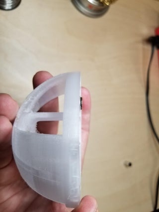
Secure the neopixel chain inside each half. The half with the deeper box is where the 15cm length should be. Do a dry run placing the chain and the mini breadboard, so you can see where the wires should be connected and run. Each neopixel can be secured to
Use a glue gun to secure the battery under the box that holds the breadboard. Remember to orient the power cable in a way that can reach the JST board.
Secure the magnets. Preferably we want the height of our rare
earth magnets to reach just to the edge of the hole so that there is no gap between the halfs when they are together. Depending on how tall your magnets are, you may need to file them down.
I found that no glue was needed to secure the rare earth magnets, but if you find that yours fall out, I would try the glue gun first and then some 2 part epoxy if that still does not hold.
To help ensure the 2 halves always connect with the correct rotation, I put 1 of them with different polarity than the other 2 (see picture describing this). Carefully ensure you have this figured out for the other side or… well, it will be bad.
Press the small grey circle grill pieces into each half. I did not need any glue to keep mine in place. This is difficult to do after the outer pieces are in place, so do this first.
Use a hot glue gun to secure the outer sphere pieces to the inner sphere halves. Remember that the outer pieces are mirrors of each other, so it does matter which side you put them on.
More detail on these steps can be found in the full-length video as I demonstrate many of the processes.
Step 5: The End
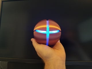
And now you have one outstanding
Cosplay prop, piece of deskage, conversation starter, party trick, you name it, its yours now!
A video of this whole process can be found here
Source: Metroid Morph Ball