Summary of Measuring the Boiling Point of Liquefied Gases Using Arduino and PhyPhox
This article details a DIY project to measure the boiling points of liquefied gases, which typically occur below 0°C. Using an Arduino Nano, a waterproof DS18B20 sensor, and a custom conical probe made from a plastic dropper, the system captures temperature data. This data is transmitted via Bluetooth Low Energy to a smartphone running the PhyPhox app, which also utilizes the phone's barometric pressure sensor to correct the boiling point value to standard atmospheric conditions. The setup allows for preliminary identification of gases like refrigerants and dust cleaners by comparing measured boiling points against known values.
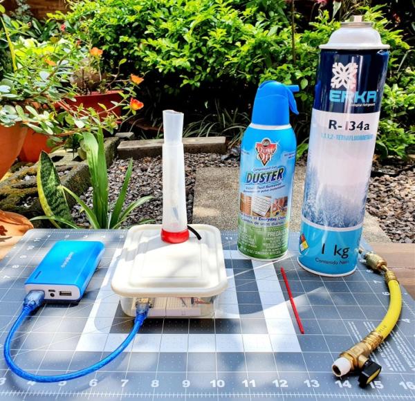
Parts used in the Measuring Boiling Point of Liquefied Gases:
- Cell Phone with barometric pressure sensor
- PhyPhox app
- 40 ml Plastic dropper pump (Good Cook brand)
- Plastic container
- Waterproof DS18B20 temperature sensor
- 2 Breadbord mini modular
- Arduino Nano V3.0 CH340 with mini usb cable
- Bluetooth Low Energy BLE CC2541 Bluetooth 4.0 UART
- 1k ohm resistance
- 2k ohm resistance
- 4,7k ohm resistance
- Male/Male jumpers wire
- Male/Female jumpers wire
- Portable battery charger (6000 mAh 3.7V)
- Cutter knife
- Silicone glue
- Plastic fasteners
A substance that is in a liquid state is constantly evaporating or passing into the gaseous state (depending on the intermolecular forces and temperature). The pressure exerted by the gaseous molecules produced in this process is known as vapor pressure.
The vapor pressure depends on the temperature in such a way that at higher temperature higher vapor pressure. The temperature at which the vapour pressure equals atmospheric pressure is known as the boiling point.
In the case of liquefied gases contained in pressure vessels, such as gases used to clean dust, liquefied petroleum gas (LPG) or refrigerant gases, the pressure at which they are kept in the vessel allows a fraction of the gas to be in a liquid state.
If this liquid is removed from the vessel and subjected to atmospheric pressure it will begin to evaporate so it will take energy from the surrounding environment lowering the temperature around it. Under these conditions the vapour pressure of the liquid equals the atmospheric pressure and the liquid therefore reaches its boiling point.
The aim of this Instructable is to measure that boiling point, which as these are liquefied gases will normally be below 0°C, using an Arduino microprocessor and a waterproof DS18B20 temperature sensor capable of measuring temperatures up to -55°C.
The data will be transmitted via Bluetooth to a cell phone provided with the PhyPhox app that will not only allow us to graph and analyze the data but also have access to the sensors of the cell phone, in this case the barometric pressure meter, which will allow us to program the app to correct the boiling point value measured to its standard value referring to atmospheric pressure at sea level or 1 atmosphere.
The measured boiling point, in conjunction with other physical tests, e.g. sound speed, can be used for preliminary identification of gaseous substances.
Supplies
- Cell Phone (Android or iOS) with barometric pressure sensor (see examples in PhyPhox Sensor DataBase).
- PhyPhox app (Google Play or AppStore).
- 1 40 ml Plastic dropper pump (Good Cook brand).
- 1 Plastic container.
- 1 Waterproof DS18B20 temperature sensor.
- 2 Breadbord mini modular.
- 1 Arduino Nano V3.0 CH340 with mini usb cable.
- 1 Bluetooth Low Energy BLE CC2541 Bluetooth 4.0 UART.
- 1 1k ohm resistance.
- 1 2k ohm resistance.
- 1 4,7k ohm resistance.
- Male/Male jumpers wire.
- Male/Female jumpers wire.
- 1 Portable battery charger (6000 mAh 3.7V, Out 5V, Output Max. 2.4A).
- Cutter knife.
- Silicone glue.
- Plastic fasteners.
Step 1: Measuring Probe
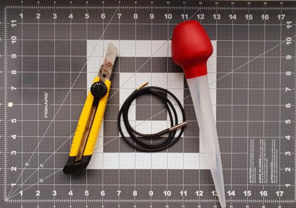
The measuring probe is basically a conical vessel that is inserted at its narrow end by the DS18B20 temperature sensor leaving enough volume of the cone to completely cover the sensor approximately 5 cm above the end of this one.
As a conical container, a plastic dropper pump (40 ml) was used that was cut into two parts, being the narrowest conical end to which the temperature sensor were adjusted and the wider conical end, next to the pump, used as a base.
The assembly fits a plastic container that serves as a support and box to hold the Arduino circuit.
The following is the procedure for constructing the measuring probe (see images):
Note: Before mounting the DS18B20 temperature sensor perform the calibration indicated in Step 2.
- Cut the plastic dropper pump to the height of the 15 ml mark (Caution: cutting hazard).
- Insert the DS18B20 temperature sensor into the narrowest conical end so that the entire metal body is inside the cone. If necessary increase the diameter of the dropper tip to adjust the sensor.
- Fix the sensor using silicone rubber or some other low temperature resistant glue. Let dry.
- Drill a hole in the wider conical base with a diameter that allows the DS18B20 temperature sensor cable to be inserted.
- Insert into the wide conical base invertedly the conical piece with the sensor inserted passing the cable through the hole previously drilled.
- Drill a hole in the lid of the plastic container that will serve as a container of the Arduino circuit of such a diameter as to allow the dropper to be inserted by its wider base.
- Attach the rubber pump to the base of the dropper, under the lid of the plastic container, so that it is fixed to it.
- Collapse the rubber pump in such a way as to serve as the base for the dropper.
- Drill a hole at the top of the plastic container cover with a diameter that allows the DS18B20 temperature sensor cable to be inserted.
- Attach the breadboard to the inside of the plastic container and install the Arduino Nano and other electronic elements (see “Arduino Connections, Code and Sensor Calibration” Step 2).
Step 2: Arduino Connections, Code and Sensor Calibration
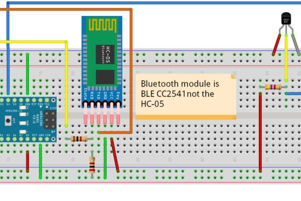
The connections of the measuring probe to the Arduino controller are shown in a Fritzing scheme that is attached (ArduinoBolingPoint.fzz). Also attached is the programming code of the Arduino Nano V3.0 CH340 (BolilingPoint_1.ino).
It should be noted in this code that the double CorrecTemp constant is a correction that should be applied to the initial measurement of the DS18B20 temperature sensor as a calibration and that it must be determined for each individual sensor being used.
This correction is estimated by reading the temperature value that the sensor marks when immersed in an ice bath (ice in the presence of liquid water). The deviation of 0°C, which is the value that the ice bath should have, is the one used as a temperature sensor correction.
In this case the measured correction value was -0.12°C and the data were read directly from the Serial Monitor of the Arduino IDE.
Note: Perform the correction procedure before assembling the temperature sensor into the probe as detailed in Step 1 as it is easier to do so with the loose sensor.
// BoilingPoint_1
// IDE 1.8.5
// Adapted and modified by Alberto Villalobos (IDE 1.8.5)
// Referencias
// <a href="https://randomnerdtutorials.com" rel="nofollow"> www.HowToMechatronics.com
</a>
// <a href="http://www.HowToMechatronics.com" rel="nofollow"> www.HowToMechatronics.com
</a>

#include <AltSoftSerial.h>
#include <OneWire.h>
#include <DallasTemperature.h>

AltSoftSerial BTserial(9, 8); // RX | TX
//  Pins
//  BT VCC to Arduino 5V out.
//  BT GND to GND
//  Arduino D8 (SS RX) - BT TX no need voltage divider
//  Arduino D9 (SS TX) - BT RX through a voltage divider (5v to 3.3v)

// Data wire is conntec to the Arduino digital pin 4
#define ONE_WIRE_BUS 4

// Setup a oneWire instance to communicate with any OneWire devices
OneWire oneWire(ONE_WIRE_BUS);

// Pass our oneWire reference to Dallas Temperature sensor
DallasTemperature sensors(&oneWire);

double Temperatura;
double CorrecTemp = -0.12; //Corrección a la temperatura medida inicialmente por el sensor

void setup()
{
  // Start serial communication for debugging purposes
  Serial.begin(9600);
  BTserial.begin(9600); // HC-06 default serial speed is 9600
  // Start up the library
  sensors.begin();

}

void loop(){
  // Call sensors.requestTemperatures() to issue a global temperature and Requests to all devices on the bus
  sensors.requestTemperatures();

  Temperatura = sensors.getTempCByIndex(0) + CorrecTemp;

  BTserial.print(Temperatura);
  BTserial.print("/");
  Serial.println(Temperatura);

  delay(100);
}<br>
Step 3: PhyPhox Parameters and Installation
PhyPhox is an application that allows access to cell phone sensors (accelerometer, magnetometer, pressure, etc.) that allows you to perform ready-to-play Experiments (sensors, acoustics, tools, mechanics, timers, everyday life) analyze data and save the results.
The application also allows you to design your own Experiments using both cell phone sensors and external sensors (connected via bluetooth), through an online editor (Editor-Test) in which you can define relationships between the captured data, graph the data and save the results.
This is the case of this Instructable in which an application for PhyPhox (Boiling Point.phyphox) was designed to combine external temperature measurements (captured and transmitted via bluetooth by an Arduino microprocessor) and barometric pressure measurements recorded by the pressure sensor of a cell phone.
With the data measured by the sensors, the analysis of the information is performed by the PhyPhox app installed on the cell phone which makes the device designed independent of a desktop or laptop computer.
The specific parameters that make up the experiment designed in this Instructable (Boiling Point.phyphox) are shown in the video attached to this Step as well as the procedure necessary for loading experiment on the cell phone.
Details on how to design an experiment using online editor for PhyPhox can be found in the Experiment Editor PhyPhox website.
While the process of designing the Experiment is quite intuitive I would like to place special emphasis on some points which, in my experience, were crucial to making communication between the Arduino and the cell phone using PhyPhox.
The above points are related to the Input tab of the Editor-Test and have to do with Bluetooth device parameters called “Device Name” and “characteristic”.
To find out these parameters Arduino microprocessor connections listed in Step 2 must be made and the armed equipment connected to the portable battery. Under these conditions the Bluetooth device will start issuing information, including the parameters we want to find out.
There are many mobile phone applications that allow us to access this information, in our case one was used for Android called BLE Analyser (free with advertisements) that allowed us to recognize the Name of our device as well as the Custom Characteristic that is the one we specifically need (see explanatory image in this Step).
There is another parameter that we need to know and that is also requested in the Input tab of the Editor-Test, is the so-called “separator” and that relates to the character used by Bluetooth to separate the data that is transmitted. This character is defined in the programming of the Arduino file and in our case is set with the symbol “/” (see explanatory image in this Step).
Pro Tip 1: A simple way to understand how the online editor works is to load Experiments to the Editor-Test from those included in the app.
Pro Tip 2: PhyPhox is designed to use low-energy bluetooth emitters (LBE) so you need to ensure the use of this kind of device.
Step 4: Measurement and Conclusions
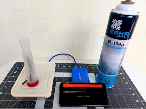
Measurement Procedure:
As an example of liquefied gases that were measured by the boiling point using the procedure described in this Instructionable, a commercial dust cleaner (Dust-Off Duster) and two technical refrigerant gases (Erka R-134a and Genetron 22) were used.
These three products are contained in pressure vessels containing a mixture of gas (top) and liquid (bottom) that are extracted through a valve fitted with a tube or hose, which in the case of the Erka R-134 comes as part of the vessel, and in the case of the other two gases comes separately and must be installed at the time of use.
The measurement procedure in all three cases is described below:
Note: do this operation in a ventilated site and away from heat sources or open flames! Wear safety glasses and insulating gloves!
- Activate the PhyPhox app on your cell phone.
- Select Boiling Point from the Experiments menu.
- Select the Bluetooth device corresponding to the armed Arduino device.
- Press the Play (pulsating button) in the app to start capturing data.
- Invert the cylinder to access the liquid fraction of the sample, direct the outlet hose to the mouth of the conical vessel of the measuring probe and slowly and carefully open the valve until the liquid flows and fully covers the DS18B20 temperature sensor (Caution: Danger of freezing).
- Observe the temperature drop curve in the “Temperature” tab of the app until it reaches its minimum and stabilizes for at least 1 minute, then read the boiling point measurement in the “Boiling Point” tab.
- If desired, you can save the temperature curve data by pressing the three buttons in the upper-right corner of the app and selecting Export Data.
- Once the measurement is finished discard the excess sample by emptying it to the ground, the liquid will evaporate immediately (Caution: Danger of freezing).
Conclusions:
As noted in the results chart included in this Step, the difference between the measured boiling point and the one reported in the literature (1, 2, 3, 4) was in the order between 0.08°C and 0.36°C for an average of 0.2°C which can be considered an acceptable value given the simplicity of the equipment used.
Possible causes of deviations found could include:
- That no distilled water was used for calibration at the freezing point of the water but pipe water that has a slightly lower freezing point.
- That the calibration of the temperature sensor was performed using a single point (freezing point of water) being recommended with all measuring equipment to make measurements at various temperatures and at points that cover the expected values for the samples under study.
- That the purity of the gases is not known and that if it is not 100% a reported boiling point deviation should be expected.
- That the Sydney-Young constant (Ksy) used in the barometric pressure correction equation corresponds to a generalization for non-polar compounds and that it does not necessarily fit perfectly with the type of compounds used.
- That you can also expect errors in barometric pressure measurements obtained from the cell phone pressure sensor.
Notwithstanding all of the above, the values are close enough to the expected values to provide evidence, in conjunction with other physical determinations, to identify the substance under study.
Note: This Instructable is a hobby project designed to perform approximate boiling point measurements as a means of identifying liquefied gases.
For more accurate measurements and more reliable identification, the thermometer sensor must be calibrated using reference substances covering the range of samples to be identified. Calibrations must also be performed at different altitudes to validate the cell phone pressure sensor, among other technical requirements.
References:
- 1,1-Difluoroethane
- 1,1-Difluoroethane_Technical data sheet
- 1,1,1,2-Tetrafluoroethane
- Chlorodifluoromethane
Source: Measuring the Boiling Point of Liquefied Gases Using Arduino and PhyPhox
- What is vapor pressure?
The pressure exerted by gaseous molecules produced when a liquid evaporates. - How is the boiling point defined in this context?
It is the temperature at which the vapor pressure equals the atmospheric pressure. - Can the boiling point be measured below zero degrees Celsius?
Yes, for liquefied gases, the boiling point is normally below 0°C. - Which sensor is used to measure temperatures down to -55°C?
A waterproof DS18B20 temperature sensor is used for this purpose. - How does the system correct for atmospheric pressure differences?
The PhyPhox app uses the cell phone's barometric pressure meter to correct the measured boiling point to sea level standards. - How is the temperature sensor calibrated before use?
The sensor is immersed in an ice bath containing liquid water to determine the deviation from 0°C. - What specific software is required on the mobile device?
The PhyPhox app is required to graph data and access the barometric pressure sensor. - How is the measuring probe constructed?
A 40 ml plastic dropper pump is cut into two parts, with the narrow end housing the temperature sensor and the wider end serving as a base. - What are the potential causes for deviations in measurement results?
Deviations may be caused by using non-distilled water for calibration, single-point calibration, unknown gas purity, or errors in the cell phone pressure sensor. - Is this project suitable for high-precision identification?
No, it is designed for approximate measurements; accurate identification requires calibration with reference substances covering the sample range.