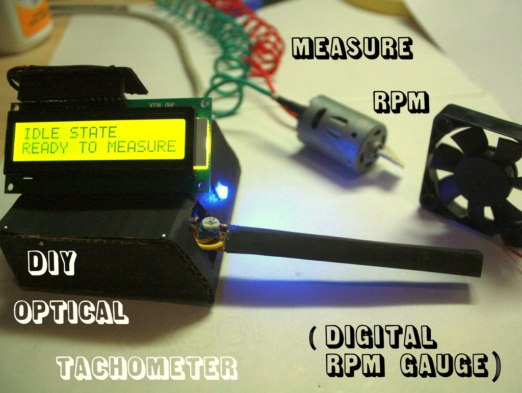
Summary of Measure RPM – Optical Tachometer using Arduino
This project describes how to build a Portable Digital Optical Tachometer using an Arduino Uno with an improved reflection-based sensor instead of a slotted sensor. This design measures RPM up to 20,000, works up to 7-8 cm sensor range, automatically toggles between idle and reading modes, supports ambient light adjustment, and offers an LCD display along with customization options. The sensor uses an IR LED and photodiode for non-contact RPM measurement, suitable for various rotor types. The guide details sensor construction, component assembly, and programming.
Parts used in the Portable Digital Optical Tachometer:
- Arduino Uno
- Resistors (33k ohm, 270 ohm)
- 10k potentiometer
- Blue LED
- Infrared (IR) LED
- Photodiode
- 16 x 2 LCD display
- 74HC595 shift register
- 3-wire ribbon cable
- Perfboard
- Headers
- Soldering iron
- Solder
- Pins
- Screws
- Motors and DC fan (for testing)
This Instructable will show you how to make a Portable Digital Optical Tachometer using an Arduino Uno. This project is inspired from This instructable and is an enhanced version of it with an LCD display and a modified code.
Instead of a slotted sensor , it has a reflection based sensor. So :
1. You don’t have to worry about the thickness of the rotor
2. The number of blades won’t change your readings
3. It can also read the RPM of drum style rotors which slotted sensor can’t
What is a tachometer ?
A tachometer is a device used to measure the RPM or Revolutions Per Minute of any rotating body. Tachometers can be contact based or non-contact ones. The non-contact or contact-less optical tachometers usually use laser or Infrared beam to monitor the rotation of any body. This is done by calculating time taken for one rotation.
FEATURES
Step 1: Part List :
Step 2: Build the sensor
For the sensor you’ll need an IR LED and a Photodiode.
1. Start by sanding the LED and photodiode to make it flat ( do not sand it too much or you’ll destroy it ).
2. Then fold a strip of paper sheet as shown. Make two such Structures so that the LED and Photodiode fit tightly into it. Joint these together by glue and paint them black.
3. Insert your LED and Photodiode in them in such a way that the positive ( longer ) lead of the LED is right above the shorter lead of the photodiode.
4. Glue them into the cover using superglue and solder the positive ( longer ) lead of the LED to the shorter lead of the photodiode.
5. Solder the 3 wire ribbon cable to the remaining leads
In my case :
1. Orange wire –> LED’s positive pin and photodiode’s shorter lead
2. Yellow wire –> photodiode’s longer lead
3. Green Wire –> LED’s ground pin
You’re ready to make the board >>
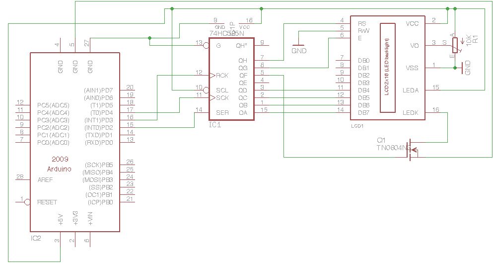
Step 3: Making the sensor board
Take a small piece of Perfboard and place the components according to the schematics.
The resistor values may vary depending on what kind of photodiode are you using.
The potentiometer helps in reducing or increasing the sensitivity of the sensor.
Finally solder the sensor wires as shown and solder 3 headers.
The headers ( in order ) are shown on the left side of the schematic.
make a cuboidal paper tube whose length is equal to the sensor wires.
For more detail: Measure RPM – Optical Tachometer using Arduino