Summary of How To Measure Distance Between Two Ultrasonic Sensors
This article explores using two HC-SR04 ultrasonic sensors to measure distance between them, enabling triangulation for applications like robot docking. The author notes challenges in accuracy and shares a modified understanding of the sensor's Echo pin behavior, which goes high immediately after triggering rather than waiting for the return wave.
Parts used in the Ultrasonic Sensor Distance Measurement Project:
- Arduino (2 Nos)
- HC-SR04 Module (2 Nos)
Ultrasonic sensor (HC-SR04) is commonly used to find the distance of an object from one particular point. It has been fairly easy to do this with the Arduino and the code is also pretty simple. But in this article we are going to try something different with these popular HC-SR04 sensors. We will try calculating the distance between two Ultrasonic sensors that is, we will make one sensor to act as transmitter and the other sensor to act as receiver. By doing this we can track the location of one transmitter using many ultrasonic receivers this tracking is called triangulation and can be used for automatic docking robots luggage followers and other similar application. Finding the distance between two US sensors might sound to be a fairly simple task but I faced few challenges which are discussed in this project.
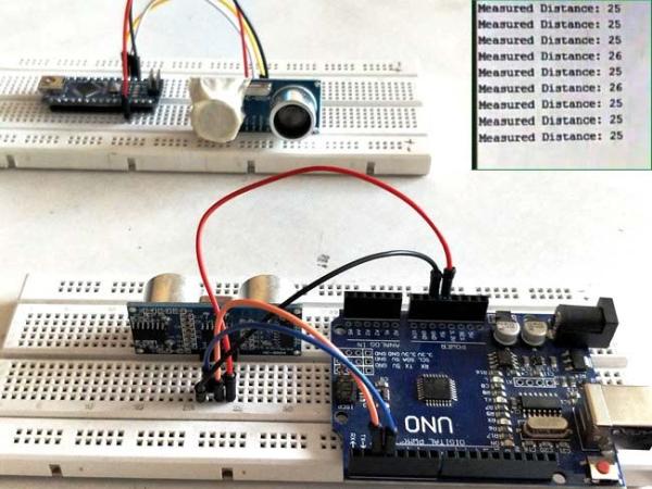
The technique discussed in this article is not fairly accurate and might not be useful in any real systems without modifications. During the time of this documentation I did not find anyone getting results as close as mine so I have just shared my views on how I got it to work so that people who are trying this need not re-invent the wheel.
Materials Required:
- Arduino (2Nos) – Any model
- HCSR04 Module (2Nos)
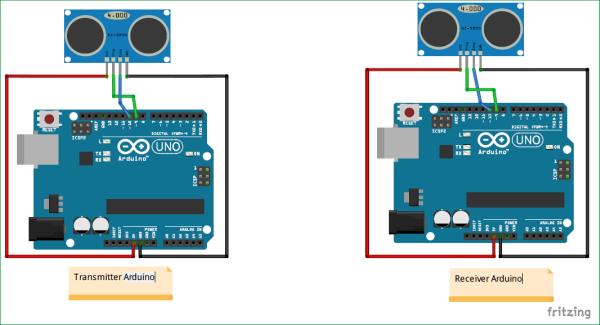
Even though we are going to make one US (Ultrasonic) sensor to work as transmitter and the other as receiver it is mandatory connect all the four pins of the sensors with the Arduino. Why should we? More of that will be discussed later.
As you can see the circuit diagram for both Transmitter and receiver are both identical. Also check: Arduino Ultrasonic Sensor Interfacing
How HC-SR04 module actually works:
Before we proceed any further let us understand how the HC-SR04 sensor works.
The sensor has two pins Trigger and Echo which is used to measure distance as shown in the timing diagram. First to initiate measurement we should send an Ultrasonic wave from the transmitter, this can be done by setting the trigger pin high for 10uS. As soon as this is done the transmitter pin will send 8 sonic burst of US waves. This US wave will hit an object bounce back and will be received by the receiver.
Here the timing diagram shows that once the receiver receives the wave it will make the Echo pin go high for a duration of time which is equal to the time taken for the wave to travel from US sensor and reach back to the sensor. This timing diagram does not seem to be true.
I covered the Tx (transmitter) part of my sensor and checked if the Echo pulse got high, and yes it does go high. This means that the Echo pulse does not wait for the US (ultrasonic) wave to be received by it. Once it transmits the US wave it goes high and stays high until the wave returns back. So the correct timing diagram should be something like this shown below (Sorry for my poor writing skills).
Read More: How To Measure Distance Between Two Ultrasonic Sensors
- What is the primary goal of this project?
To calculate the distance between two ultrasonic sensors by making one act as a transmitter and the other as a receiver. - Can this technique be used for real systems without modifications?
No, the technique is not fairly accurate and might not be useful in real systems without modifications. - How many Arduino boards are required for this setup?
Two Arduino boards of any model are required. - How do you initiate an ultrasonic measurement?
You must send an ultrasonic wave from the transmitter by setting the trigger pin high for 10 microseconds. - How many sonic bursts does the transmitter send?
The transmitter sends 8 sonic bursts of ultrasonic waves. - Does the Echo pin wait for the wave to return before going high?
No, the Echo pin goes high immediately after transmitting the wave and stays high until the wave returns. - What application can triangulation support?
Triangulation can be used for automatic docking robots, luggage followers, and similar applications.