Summary of The MAX7219 and MAX7221 Led drivers
Concise summary (under 100 words): The article explains using Maxim MAX7219/MAX7221 LED driver ICs with Arduino to control 64 LEDs or up to eight 7-segment digits via an SPI-compatible 3-wire interface. It covers required external components (two capacitors and an RSet resistor), wiring to Arduino, cascading multiple drivers, LED/7-segment wiring, and power-supply considerations including USB vs external/battery power. Emphasis is placed on reading the official datasheet first and placing decoupling capacitors close to V+ and GND.
Parts used in the MAX72XX LED/7-segment driver project:
- MAX7219 or MAX7221 LED driver IC (referred to as MAX72XX)
- Arduino board
- Capacitor C1 (decoupling capacitor near V+)
- Capacitor C2 (decoupling capacitor near GND)
- Resistor RSet (current-setting resistor)
- LED matrix or individual LEDs or 7-segment displays
- Wires/cables for DIn, CLK, Load(/CS), V+, and GND
- Optional external 5V power supply or batteries (when more power needed)
These two integrated circuits from Maxim are for driving either 64 individual Led’s, or up to 8 digits of 7-segment displays. The drivers implement a SPI compatible slave interface that can be controlled from the Arduino using only 3 of the digital output pins. An extensive datasheet for the IC’s is available from the Maxim homepage. Since both chips are very similar, I will use the term MAX72XX for both the MAX7221 and the MAX7219.
I will focus on building the Led driver hardware, so this article should be considered as only a supplement to the original datasheet.
In other words : First read the original datasheet, then read this article for some extra Arduino-info.
Table of contents
- Wiring and schematics
MAX7219andMAX7221what makes them different?- Selecting a value for
RSet - Power supply issues
Wiring and schematics
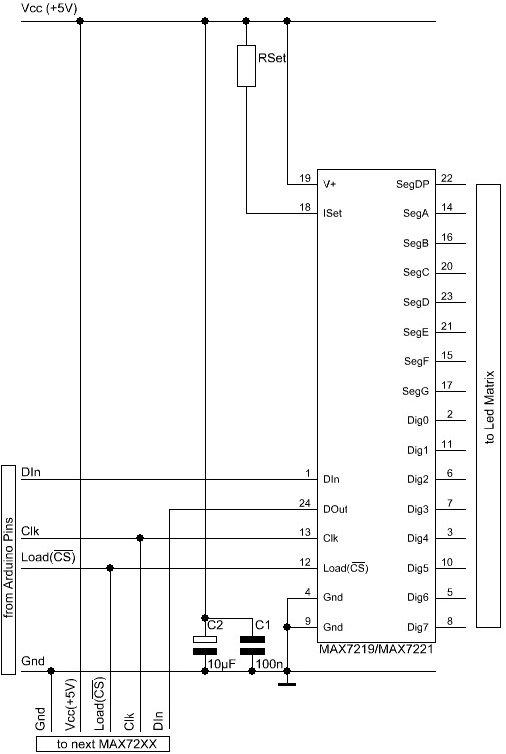
Here is a basic schematic for a MAX72XX, showing the data signals coming from the Arduino.
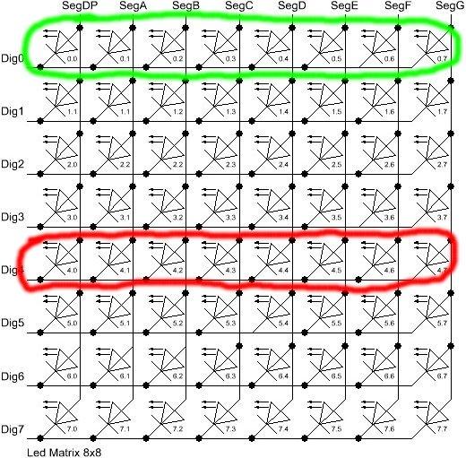
There are not yet any Leds in the schematic. There will be an extra section on Led wiring.
Besides the MAX72XX itself and the Leds you need only 3 external components: two capacitors (C1;C2) and a resistor (RSet).
The capacitors are there to supress noise signals introduced through the power-supply lines. By no means these 2 capacitors can be ommitted, as it might lead to sporadic or permanent malfunctions. These types of errors are really hard to track down. Both capacitors must be placed as near as possible to the V+ and the Gnd pins of the MAX72XX.
The resistor RSet is responsible for setting an upper limit on the current that is fed into the Leds. Selecting the correct resistor value might not be trivial. There is an in-depth discussion on this later.
The MAX72XX has to be powered with +5V. For a single Led-matrix it is possible to use the +5V supply from the Arduino-board. If you add more than one matrix to the Arduino you will probably need an external power-supply. More on this in section Power supply issues.
Wiring the Arduino
The Gnd-Pins of the MAX72XX have to be connected to one of the Gnd-Pins on the Arduino board. That makes both circuits work on the same voltage-level. The positive power-supply pins (+5V/Vcc) can be connected to the Arduino-board for a limited number of Led’s.(See Power supply issues for details.)
The three signal lines (DIn,CLK,Load(/CS)) have to be connected to three digital outputs on the Arduino board. It depends on the software which Arduino pins have to be used. For the exact pin-numbers you have to refer to the documentation of the library or the example code on which you build your project. With most of the libraries for the MAX72XX you are free to choose any pins you like.
If you read the datasheet for the MAX72XX you know that the drivers can be cascaded by simply connecting the signal DOut from one chip to DIn on the next chip. The signals Clk and Load(/CS) have to be connected in parallel to each MAX72XX. There is no strict limit as to how many drivers can be cascaded that way. But the SPI-interface is not capable of any error checking on the transmitted data, so you are already limited with the length of the cables that run from one MAX72XX to the next one. If your cables get longer than 10cm between each MAX72XX you might already run into trouble.
For more detail: The MAX7219 and MAX7221 Led drivers
- What external components are required with the MAX72XX?
Two decoupling capacitors (C1 and C2) and a current-setting resistor RSet are required. - Can I power the MAX72XX from the Arduino 5V supply?
Yes for a single LED matrix, but multiple matrices likely require an external power supply. - How many Arduino pins are needed to control the MAX72XX?
Three Arduino digital outputs are required for DIn, CLK, and Load(/CS). - Can MAX72XX chips be cascaded?
Yes, by connecting DOut of one chip to DIn of the next, with Clk and Load(/CS) in parallel. - Do the decoupling capacitors have to be placed in a specific location?
Yes, both capacitors must be placed as near as possible to the V+ and GND pins of the MAX72XX. - What does RSet do?
RSet sets an upper limit on the current fed to the LEDs. - Are there limits to cable length between cascaded MAX72XX chips?
Yes, cables longer than about 10 cm between chips may cause communication problems. - Do I need to read the datasheet before using the article instructions?
Yes, the article advises reading the original Maxim datasheet first and using the article as a supplement for Arduino-specific information.