There are many CAD developed to assist the electronic designers during drawing of PCBs and schematics; often they are integrated in complete suite to project, simulate and realize a whole electronic system. Besides the many commercial versions, there are also free CADs available. Today we’d like to analyze one of the most diffused and known software: Eaglecad (eagle does not mean the powerful bird but it is the acronym of Easily Applicable Graphical Layout Editor) made by Cadsoft, actually at version 6.2.0. We have chosen this one because, as you know as an Arduino’s fan, the official pcbs and schematic files of the boards are developed and available free of charge to everybody in Eaglecad format; you can find also a lot of libraries and circuits made by famous DIY website (Sparkfun for first) available for free. Eaglecad is a professional software that have gained a lot of popularity due to the Arduino’s success. One of the most important difference between Eaglecad and its competitors is the availability of a version for every of the most common desktop OS: Windows, Linux, Mac.
We have to specify that Eaglecad is not Free software but is a commercial one, which can be used in the free version (eaglecad light) only for evaluation purposes and by student but you can’t use the light version in any case when you earn or save money by using it. For further details about licenses and distributors have a look to the official Eaglecad website where you can find all the information you need. Remember that the light version has some limitations; anyway you can design circuit with a discrete complexity, as the one you can see at http://elmicro.com/en/kit12.html. The limitations are:
– pcb dimensions not bigger than 100×80 mm;
– no more than 2 layers;
– only 1 sheet for schematic
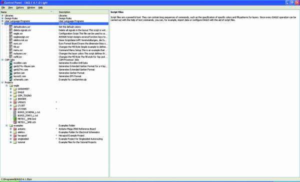
Now let’s have a look at the software itself starting from the GUI, which is made by three main units:
Control Panel
 Board (the pcb editor) which can be seen “in action” which shows the pcb of the Arduino’s R3 board
For people used to the other similar cads, the interface is very closed to them and you’ll learn to use it easily; anyway to use the most powerful functions you need some practice.
The first thing you see at the CAD start up is the Control Panel, from which you can easily get access (for example) to the libraries, projects and examples; this is the software section where you can configure the main options like user’s folders, delay for the autosave option and the most important graphical parameters, all by getting access to the “OPTIONS” menu. The available documentation is pretty complete: you can access to the help function from the “help” menu available in both “Schematic” and “Pcb”. If you need further details you have to read the complete manual and the tutorial which are both available getting access to “Start” (on Windows), Programs-> Eagle Layout Editor 6.2.0.
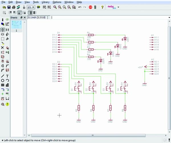
Let’s try to have practice with an example: we want to draw an Arduino’s shield made by 4 leds e da 4 switches, connected to 8 digital pins; it’s obvious due to the kind of circuit we are approaching to make, that this shield is only for training purposes. This pcb can be used to show the digital logic level of one or some pins, levels that could be changed by the four switches or to have a led alarm in case of an analog becomes higher or lower than some level.
For first we have to draw the schematic so we select “FILE”, “NEW”, “SCHEMATIC” in this order: the Schematic window will open up. It is mainly made by two groups of icons: one on the top with the main commands like file management and zoom and another one on the left with the “drawing” icons.
For more detail: How to make an Arduino shield with Eagle CAD – Tutorial

