
Summary of Light and Water Reactive Raincoat
The author created a light and water-reactive raincoat for a "Computing and Craft" class to enhance safety during sudden weather changes. The project integrates microcontrollers with wearable craft, featuring LEDs that illuminate in the dark and a buzzer that warns of wet conditions. The build involved reinforcing a cheap plastic coat, sewing conductive threads, and designing custom circuits using an Arduino, sensors, and resistors to achieve responsive functionality.
Parts used in the Light and Water Reactive Raincoat:
- Plastic raincoat
- Sewing machine
- Arduino microcontroller
- 8 LEDs
- Conductive thread
- Needle-nose pliers
- Solderless breadboard
- Water sensor
- Light sensor
- 1M resistor
- Buzzer (implied by warning beep)
This semester at college, I am in a class called Computing and Craft which is about incorporating circuitry and micro-controllers and craft to bring our projects to the next level.
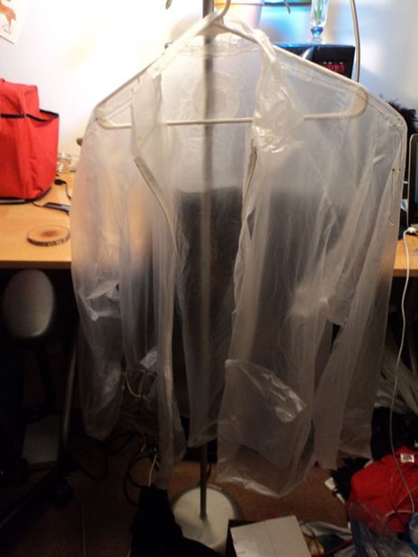
For our first big project, I decided to make a raincoat the reacted to light and water. Being from California and going to school in Massachusetts has been a big transition and the sudden downpours can catch you unaware. This raincoat has built in light and water sensors so when it gets dark the raincoat lights up so the wearer will be visible in the dark, and when it gets wet, a warning beep sounds so the wearer can head for cover.
Step 1: Raincoat
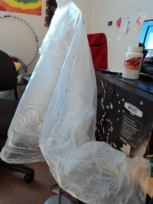
For the coat itself, I used a very cheap plastic one that my professor had around. I reinforced all the seams on the sewing machine because they had all just been melted together and were coming apart. The coat also had pockets which was convenient for storing the arduino.
Step 2: Circuitry
For the circuitry, I tried everything on a solderless breadboard even though everything did end up being soft circuits. 8 LEDs (4 on each sleeve) are attached by poking the leads through the plastic, winding the leads around needle-nose pliers, and then stitching them together using conductive thread. I didn’t realize just how resistive the thread was and in the future I would recommend wiring in series, not parallel as I did.
The circuits I used were based on the digram below which I got from this board. For my water sensor I ended up using a 1M resistor instead of 10k.
For the light sensor, I based my circuit off of this SparkFun inventor’s guide for the light sensor on page 24.
For more detail: Light and Water Reactive Raincoat
- What is the purpose of the light and water reactive raincoat?
The coat lights up when it gets dark to make the wearer visible and sounds a warning beep when it gets wet so the wearer can head for cover. - How were the LEDs attached to the raincoat sleeves?
The LED leads were poked through the plastic, wound around needle-nose pliers, and stitched together using conductive thread. - Did the author wire the LEDs in series or parallel?
The author wired the LEDs in parallel but recommends wiring them in series in the future due to the high resistance of the thread. - Why was a 1M resistor used instead of a 10k resistor?
A 1M resistor was used specifically for the water sensor circuit in this project. - Where did the author find the circuit diagrams for the project?
The water sensor circuit was based on a board diagram, while the light sensor circuit followed a SparkFun inventor's guide page 24. - How did the author prepare the plastic raincoat before adding electronics?
The author reinforced all the seams on a sewing machine because they had been melted together and were coming apart. - Can you use a solderless breadboard for soft circuits?
The author tried everything on a solderless breadboard first, even though the final implementation used soft circuits. - What feature of the raincoat was convenient for storing the Arduino?
The pockets on the coat were convenient for storing the Arduino.
