Summary of Introducing RFToy, an Arduino-compatible gadget for radio frequency modules
RFToy 1.0 is a compact, Arduino-compatible gadget designed for interfacing with Radio Frequency modules. It features an ATmega328p microcontroller running at 3.3V and 8MHz, equipped with an OLED display, tactile buttons, and a coin battery holder. The device supports 433/315 MHz RF modules, nRF24L01 transceivers, and includes a 3.5mm audio jack for signal monitoring. A built-in demo allows users to record, store, and replay up to seven remote control signals using the RCSwitch library.
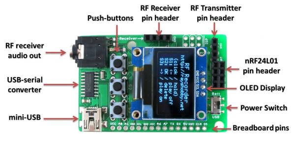
Parts used in the RFToy Project:
- ATmega328p @ 3.3V, 8MHz
- CH340G USB-serial converter
- Arduino bootloader
- Mini-USB port
- 128×64 OLED display
- Three tactile buttons
- 20mm coin battery holder
- Slide switch for power selection
- Pin headers for 433/315 MHz RF transmitter and receiver modules
- MOSFET power switches
- 3.5mm audio jack
- Pin headers for nRF24L01 transceiver
- Pin headers for external components
Introducing RFToy 1.0
Nov 9th, 2014 by ray
Today I am introducing the first version of RFToy — an Arduino-compatible gadget for interfacing with Radio Frequency (RF) modules. First, let me show you a few pictures of RFToy and a video introduction:
Features
- ATmega328p @ 3.3V, 8MHz, with CH340G USB-serial converter and Arduino bootloader.
- Programming in Arduino using the on-board mini-USB port.
- One 128×64 OLED display, three tactile buttons.
- 20mm coin battery holder, and slide switch to select between USB or battery power.
- Pin headers for plugging in 433/315 MHz RF transmitter and receiver modules, and MOSFET power switches for them.
- 3.5mm audio jack to output receiver signals to a computer’s line-in port, to monitor RF waves.
- Pin headers for plugging in nRF24L01 transceiver.
- Pin headers for connecting external components and/or breadboard experiments.
So in essence, RFToy is a 8MHz Arduino with buttons, OLED display, battery holder. It’s compact (1.5″ x 2.3″) and it’s suitable for a variety of projects involving RF modules.
Demos
As shown in the video above, I’ve written a couple of examples to demonstrate the basic features of the RFToy.
RF Recorder: this demo shows how to use RFToy to decode signals from the remote control of a typical wireless power socket, store the decoded signal in EEPROM, and play it back to simulate the remote control. You can store up to 7 different signals, allowing you to control up to 7 power sockets. The demo is based on the RCSwitch library, and it has a basic UI using the OLED display and buttons
For more detail: Introducing RFToy, an Arduino-compatible gadget for radio frequency modules
- How does the RFToy handle power?
A slide switch allows the user to select between USB or battery power via a 20mm coin battery holder. - Can I program the RFToy using standard Arduino software?
Yes, you can program it using Arduino through the on-board mini-USB port. - What is the maximum number of signals the RF Recorder demo can store?
The demo allows storing up to 7 different signals to control up to 7 power sockets. - Does the RFToy support wireless power socket decoding?
Yes, the RF Recorder demo decodes signals from typical wireless power socket remotes. - How can I monitor RF waves on a computer?
You can use the 3.5mm audio jack to output receiver signals to a computer's line-in port. - What type of microcontroller powers the RFToy?
The device uses an ATmega328p running at 3.3V and 8MHz. - Can I connect external breadboard experiments to the RFToy?
Yes, there are pin headers available for connecting external components and breadboard experiments. - Which library is the RF Recorder demo based on?
The demo is based on the RCSwitch library.