Summary of GRBL Based Coil Winder From Water Pipe
This article details the construction of a DIY coil winder using PVC pipes, an Arduino Uno R3, and GRBL firmware. The project automates the winding of copper wire for magnetic levitation coils by coordinating two stepper motor axes: a feeder axis for lateral movement and a spindle axis for rotation. The builder explains the assembly process, from fabricating the frame to calibrating GRBL parameters for precise layer stacking based on wire diameter and turn count.
Parts used in the Coil Winder:
- Arduino Uno R3
- Arduino CNC Shield V3 GRBL
- Stepper Motor Driver A4988 (2pcs)
- Stepper Motor NEMA 17 (2pcs)
- GT2 6mm Closed Timing Belt 200mm (2pcs)
- GT2 Timing Pulley 60 Teeth
- Round Bar Shaft Rod Diameter 8mm Length 400mm
- Round Bar Shaft Rod Diameter 8mm Length 200mm (3pcs)
- T8 Lead Screw 2mm Pitch with Copper Nut
- F608ZZ Ball Flanged Shielded Bearings (16pcs)
- XH2.54mm – 4P Wire Cable Double Connector (2pcs)
- 5mm DC Female Power Plug
- Power Supply 12VDC
- Clear/White Acrylic A3 size
- Empty plastic spool
- Small Rubber Guide Roller V type (2pcs)
- PVC Pipe Ø42mm fittings (Elbows, Tees, Connectors, End Caps)
- L steel supports
- Small steel pipe
- Plastic pen tips
When I was working on the Toy Magnetic Levitation project with a solenoid coil, I thought to myself, why didn’t I make a coil winder. So I took my times to build a simple coil winder based on GRBL firmware and it was made from PVC pipes. I’m willing to share how I made it, please check out video below and let’s get started.
Step 1: Supplies
Main components:
- 1pcs x Arduino Uno R3: Amazon – Banggood.
- 1pcs x Arduino CNC Shield V3 GRBL: Amazon – Banggood.
- 2pcs x Stepper Motor Driver A4988: Amazon – Banggood.
- 2pcs x Stepper motor NEMA 17: Amazon – Banggood.
- 2pcs x GT2 6mm Closed Timing Belt 200mm: Amazon – Banggood.
- 2pcs x GT2 Timing Pulley 60 Teeth, Hole diameter 8mm: Amazon– Banggood.
- 1pcs x Round Bar Shaft Rod Diameter 8mm, Length 400mm: Amazon – Banggood.
- 3pcs x Round Bar Shaft Rod Diameter 8mm, Length 200mm: Amazon – Banggood.
- 1pcs x T8 Lead Screw 2mm Pitch, 8mm Lead , Length 400mm with Copper Nut: Amazon – Banggood.
- 16pcs x F608ZZ Ball Flanged Shielded Bearings 8 x 22 x 7mm: Amazon – Banggood.
- 2pcs x XH2.54mm – 4P Wire Cable Double Connector: Amazon – Banggood.
- 1pcs x 5mm DC Female Power Plug: Amazon – Banggood.
- 1pcs x Power Supply 12VDC: Amazon – Banggood.
- 1pcs x Clear/White Acrylic, size A3, thickness 5~10mm: Amazon – Banggood.
- 1pcs x Empty plastic spool. I reused empty plastic spool that is used to coil the soldering tin wires.
- 2pcs x Small Rubber Guide Roller V type.
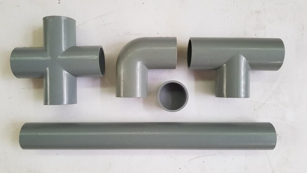
- 6pcs x Elbow PVC Pipe Ø42mm.
- pcs x Straight connector PVC Pipe Ø42mm.
- 2 meter x PVC Pipe Ø42mm.
- 12pcs x Tee PVC Pipe Ø42mm.
- 12pcs x End Cap PVC Pipe Ø42mm.
The pipe and its fittings are shown below:
Tools:
- Drilling machine with drill bit hole 22mm.
- Hand saw.
- Soldering machine.
- Big scissor.
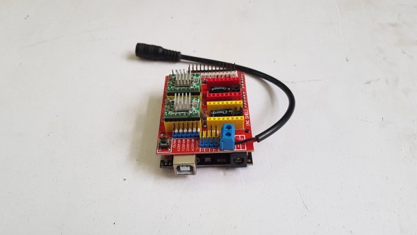
Step 2: Schematic
The connection diagram is very simple. I just plugged the CNC shield onto the Arduino Uno R3 and connected the cables to 2 stepper motors. Two stepper motor drivers A4988 were also plugged on the CNC shield at X and Y position.
There are 2 axes for a coil winder which are called:
- Feeder axis: connecting to X axis marked on CNC shield.
- Spindle axis: connecting to Y axis marked on CNC shield.
The NEXTPCB support me for this project. If you have a PCB project, please visit the NEXTPCB website to get exciting discounts and coupons.
- Only $0 for 1-4 layer PCB Prototype: https://www.nextpcb.com/pcb-quote?act=2&code=tune…
- New customer get $100 coupons, register at: https://www.nextpcb.com/register?code=tunendd
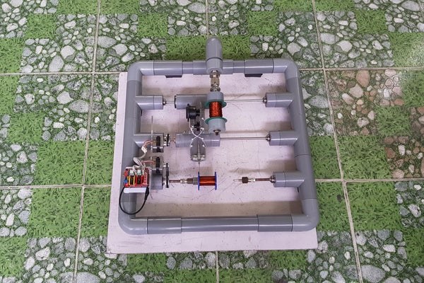
Step 3: Assembly Work
Firstly, I’ve tried to figure out how to build the coil winding machine. And it seems easy with PVC pipes. What we need is patience and carefulness.
1. Building a coil winder frame:
I assembled a square frame, dimension about 480 x 480mm. It was made of 7pcs x tees, 4pcs x elbows and connecting pipes.
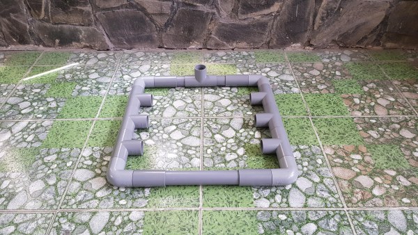
Connecting pipes should be cut in suitable length so that when we connect elbow to tee or tee to tee, there is no gap between them. With this connecting way, we don’t need to do any measurements or alignments later because they are the same size and completely symmetrical each other. As the picture above, we have 3 pairs of pipe that are completely symmetrical each other.
2. Drilling holes on the end caps for bearings and cooper nut:
Since I used a hand drilling machine, it was a bit difficult at the beginning. My goal was to drill about 12pcs x end caps with a 22mm diameter punch drill bit.
They should be drilled in the center of the end caps. When the drilling is complete, the bearings cannot be inserted into the holes. I’ve used this trick: using scissor’s back to cut around the hole by rotating in circle, it made the hole a little wider, checked them thoroughly with bearings, until bearings could be tightly inserted to the holes.
We should turn the end cap upside down, we would see the concentric circles inside the end cap and mark its center before drilling.
It is better to use flanged bearings. I only have a few of this type, the rest are normal bearings but that’s okay, when we fit tightly them into the holes, it’s strong enough.
For copper nut of leadscrew, I used a drill bit 8mm with above trick.
3. Building a feeder axis:
Feeder axis was built from 1pcs x PVC tee and 1 pcs x PVC cross. I installed end caps with bearings & copper nut at the two ends of PVC tee and cross. It looked like this.
I had one roller with 2 bearings at the ends, diameter about 42mm. I tried to put it inside the PVC tee for sliding the shaft. If we don’t have it, we can use one tee plus 2 pcs x end caps with bearings.
The leadscrew and shaft were inserted into bearings of feeder axis.
The other side view of feeder axis.
I temporarily mounted feeder axis on the coil winder frame and checked by hand how it worked.
4. Drilling stepper motors frame base
I cut one acrylic plate size 100 x 230mm, drilled 8 small holes for mounting 2 x stepper motors on it. This acrylic plate was then attached on the frame by 2 big holes whose diameter is equal outer diameter of pipe 42.
I have installed 2pcs x end caps with bearings on the front side of the stepper motors where they will be connected to the feeder axis and spindle axis.
Conecting pipes at back side would be connected to the frame. By this way, it looks neat and solid.
5. Building and mounting the spindle axis
I had some screw bolts with length x diameter about 16 x 8mm and I used them for spindle shaft. Or we can use shaft rods 200 x 8mm as mentioned on BOM list.
Acrylic base was mounted on the main frame. I installed 20 teeth pulley to the motors; 60 teeth pulley to spindle shaft; and closed timing belt 200mm.
Feeder axis was mounted on the main frame. Its pulleys and timing belt was as same as the spindle axis.
I mounting 1 screw bolts on the main frame at the other side of spindle axis and locked it by one bearing.
6. Building a uncoiling part
For uncoiling part, I used a bolt and tighten the copper coil by 2 end caps. It can rotate with a specific friction based on tighten force.
One empty spool was also connected to spindle shaft.
It looks not bad!!!
7. Building tension guide roller and copper feeder pipe.
I used some L steel supports to mount 2 rubber rollers on one acrylic sheet, then installed this tension guide roller to feeder axis
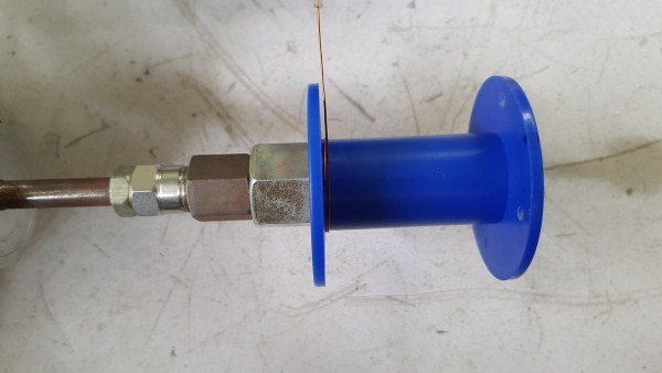
To feed the copper wire to spindle, I used one small steel pipe and inserted 2 plastic pen tips at 2 ends.
Plastic pen tips was taken from this.
Finally, I connected wires from stepper motors to CNC shield.
DONE!!!
The uncoiling part can be arranged like this, by adding one more PVC elbow. It’s easy to be rotated to get the best feeding direction.
Step 4: GRBL & UGS
1. GRBL parameters for my coil winder are as follows:
| $0 | 10.000 | Step pulse time |
| $1 | 25.000 | Step idle delay |
| $2 | 0.000 | Step pulse invert |
| $3 | 0.000 | Step direction invert |
| $4 | 0.000 | Invert step enable pin |
| $5 | 0.000 | Invert limit pins |
| $6 | 0.000 | Invert probe pin |
| $10 | 1.000 | Status report options |
| $11 | 0.010 | Junction deviation |
| $12 | 0.002 | Arc tolerance |
| $13 | 0.000 | Report in inches |
| $20 | 0.000 | Soft limits enable |
| $21 | 0.000 | Hard limits enable |
| $22 | 0.000 | Homing cycle enable |
| $23 | 0.000 | Homing direction invert |
| $24 | 25.000 | Homing locate feed rate |
| $25 | 500.000 | Homing search seek rate |
| $26 | 250.000 | Homing switch de-bounce delay |
| $27 | 1.000 | Homing switch pull-off distance |
| $30 | 1000.000 | Maximum spindle speed |
| $31 | 0.000 | Minimum spindle speed |
| $32 | 0.000 | Laser-mode enable |
| $100 | 600.000 | X-axis travel resolution |
| $101 | 4800.000 | Y-axis travel resolution |
| $102 | 250.000 | Z-axis travel resolution |
| $110 | 500.000 | X-axis maximum rate |
| $111 | 500.000 | Y-axis maximum rate |
| $112 | 2000.000 | Z-axis maximum rate |
| $120 | 5.000 | X-axis acceleration |
| $121 | 5.000 | Y-axis acceleration |
| $122 | 10.000 | Z-axis acceleration |
| $130 | 200.000 | X-axis maximum travel |
| $131 | 200.000 | Y-axis maximum travel |
| $132 | 200.000 | Z-axis maximum travel |
The important parameters which I have done the calibrations are highlighted in table above.
Details of parameters $100 and $101 are discussed in the next step.
The acceleration parameters $120 and $121 should be set to a small value, depending on the wire diameter, to prevent copper wire breakage.
2. Universal GCode Platform (UGS):
- Open Universal Gcode Platform, select Port and set Baud to 115200, click on Connect tab.
- Select the appropriate position by moving X axis left – right, rotating Y axis clockwise – counter clock wise.
- Set the original coordinates by button Reset Zero.
Step 5: How It Works
My winder works with cylindrical coils and based on GRBL firmware. To wind a copper wire in the cylindrical shape, we need the following parameters, I should give specific example:
- No. of turn: 1000.
- Coil length: 47 (mm).
- Original bobbin diameter: 27.7 (mm).
- Wire diameter: 0.3 (mm).
- Speed: 50 (rpm).
Thus, we need to stack 1000 turns of wire diameter 0.3mm in layers on a empty spool that has a length 47mm and an original diameter 27.7mm.
The major calculation is as below:
- No. of turn per one layer = Coil length/ Wire diameter = 47 / 0.3 = 156.67.
- No. of layers = Total no. of turn/ No. of turn per one layer = 1000 / 156.67 = 6.38.
To use GRBL firmware, my idea is like this:
- Feeder axis: will move right and left in the range from 0 to 47mm, with 6.38 times and its STEP/mm parameter is precisely defined according to the GRBL firmware. It will reverse when the spindle axis rotates exactly by a multiple of 156.67, that means, when one layer is completed.
- Spindle axis: will rotate exactly 1000 revolutions and then stop. Its setting in the GRBL firmware is STEP/rev. Note that is STEP/revolutions, not STEP/mm.
Because the copper wire diameter is 0.3mm, so the feeder axis would move between 0.15 and 46.85mm (minus the wire radius at 2 edges).
G-code
Following to the example above, there are a total of 6.38 layers, so the last 0.38 layer (layer 7) has 0.38 x 156.667= 60 revolutions. That means spindle axis will rotate 60 revolutions and feeder axis will move to (60*0.3 – 0.15) = 17.85 from 0.15. The feeder movement rule is:
- Odd Layer: From 0.15 to 46.85 (Move Right).
- Even Layer: From 46.85 to 0.15 (Move Left).
Source: GRBL Based Coil Winder From Water Pipe
- How is the feeder axis connected in the schematic?
The feeder axis connects to the X axis marked on the CNC shield. - What is the best way to widen drilled holes for bearings?
Use the back of scissors to cut around the hole by rotating in a circle until the bearing fits tightly. - Does the spindle axis rotate based on STEP/mm or STEP/rev?
The spindle axis setting in the GRBL firmware is STEP/revolutions, not STEP/mm. - How do you calculate the number of layers for a coil?
Divide the total number of turns by the number of turns per one layer, which is calculated as Coil length divided by Wire diameter. - Can I use normal bearings instead of flanged ones?
Yes, normal bearings are okay if they fit tightly into the holes, making them strong enough. - What acceleration settings should be used to prevent wire breakage?
Acceleration parameters $120 and $121 should be set to a small value depending on the wire diameter. - How does the feeder axis move during odd and even layers?
During odd layers it moves right from 0.15 to 46.85mm, and during even layers it moves left from 46.85 to 0.15mm. - What software is used to control the machine?
The Universal Gcode Platform (UGS) is used to connect via port and set the baud rate to 115200. - What material is used to build the main frame?
The frame is built using PVC pipes and fittings such as tees, elbows, and end caps. - How is the copper wire tension managed during feeding?
A tension guide roller made of rubber rollers mounted on L steel supports is installed on the feeder axis.