Summary of GPS Clock using Arduino
This article details the construction of a GPS-synchronized clock using an Arduino Uno R3. The system extracts time and date from the $GPRMC string provided by a SIM28M GPS receiver module via serial communication. The processed data is displayed on an LCD screen, eliminating the need for manual time setting and ensuring high accuracy suitable for various applications like transport hubs or military use.
Parts used in the GPS Clock:
- Arduino Uno R3 board
- SIM28M GPS receiver module
- GPS antenna (ANT.1)
- LCD display (LCD1)
- 9V DC power supply adaptor
- External header jumpers

Global positioning system (GPS) synchronised clocks give accurate time. These clocks are universal and commonly used at railway stations, bus stands and airports. These are widely used for military purposes too.
Here we describe a GPS clock based on Arduino Uno R3—an AVR ATmega328-based microcontroller board with six analogue inputs pins and 14 digital input/output (I/O) pins. The microcontroller has 32kB ISP flash memory, 2kB RAM and 1kB EEPROM. The board provides serial communication via UART, SPI and I2C.
Circuit and working
Figs 1 and 2 show block diagram and circuit of the GPS clock using Arduino, respectively. In addition to Arduino Uno board (BOARD1), the circuit uses SIM28M GPS receiver module (GPS1) along with a GPS antenna (ANT.1), 9V DC power supply adaptor and a few jumpers for header connections.
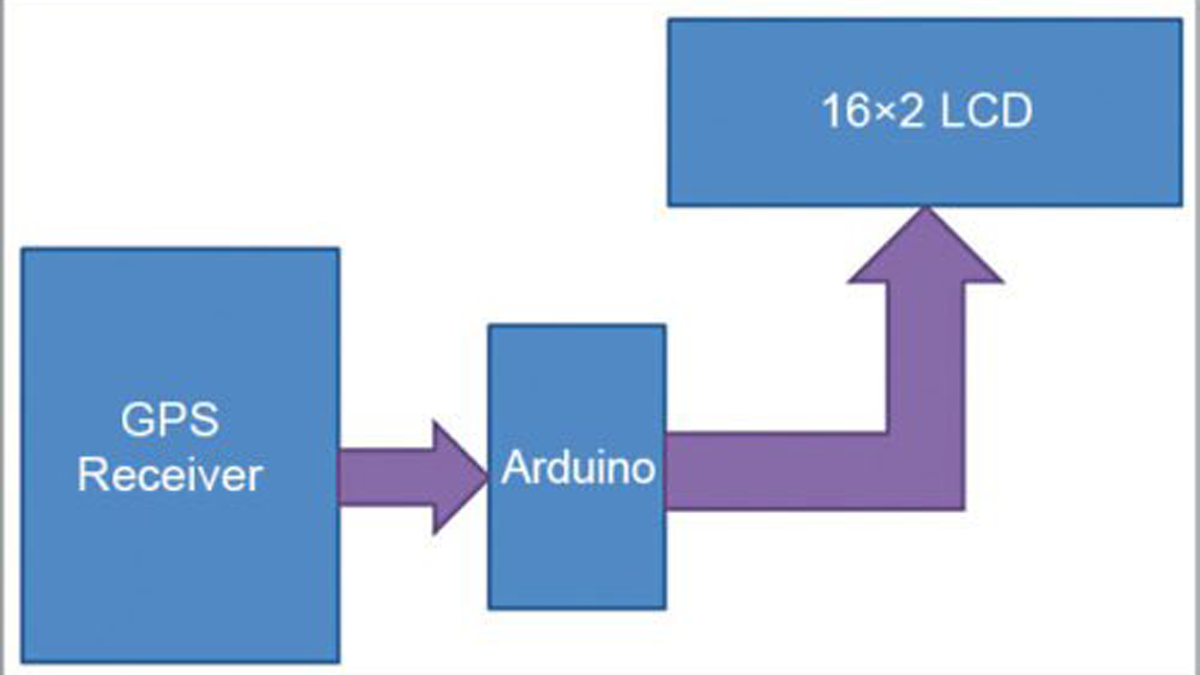
Block diagram of GPS clock using Arduino

Circuit diagram of GPS clock using Arduino
Here, we have tried to extract GPS time and date from a string ($GPRMC) that comes from GPS. This string is about 70 characters long. As shown in Fig. 2, Arduino controls all the processes and receives GPS output signals. After receiving the GPS output, Arduino reads all the strings and stores required strings in a string or in an array in the Arduino program.
After storing the required string, Arduino extracts the time and date from the stored string and sends it to LCD1 for displaying time and date.
Data pins D4 through D7 of LCD1 are directly connected to pins 5, 4, 3 and 2 of Arduino, respectively. Control pins EN and RS of LCD1 are connected to pins 11 and 12 of Arduino, respectively. GPS receiver’s Tx pin is directly connected to Rx pin of Arduino board. Note that the ground pins of Arduino and GPS should be connected to each other.
Here GPS module is operated on 9600bps baud rate. Arduino is configured at 9600bps baud rate by using class Serial.begin(9600) function in the Arduino sketch.
GPS output
The GPS receiver output can be viewed on the serial monitor of the Arduino as shown in Fig. 3. In order to get this GPS data, use the same connections as mentioned above but remove microcontroller ATmega328 from the Arduino board. Then open the Arduino IDE and select Serial Monitor option to view GPS output format.
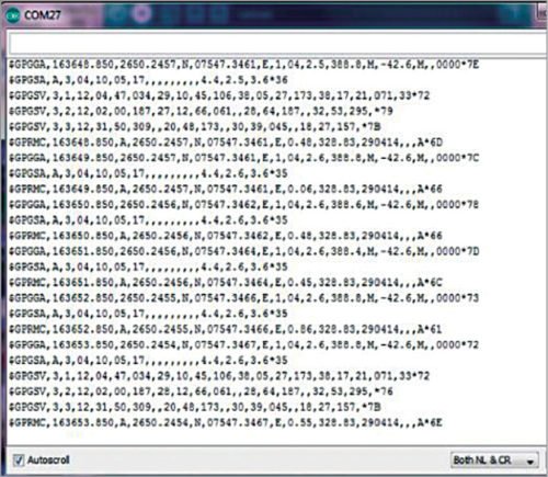
GPS output from serial monitor of Arduino IDE
This window shows many strings, of which you need to use only $GPRMC. Here, after the first comma you can see time in 24-hour format, and after the ninth comma you can see date. Arduino program extracts date and time from this $GPRMC string, processes them and displays on LCD1.
Software
Circuit operation is controlled by the software program loaded into the internal memory of Arduino Uno. The program (gpsindia.ino) is written in Arduino programminglanguage. Arduino IDE 1.6.4 is used to compile and upload the program.
Connect Arduino board to the PC and select the correct COM port in Arduino IDE. Compile the program/sketch. Select the correct board from ToolsBoard menu in Arduino IDE and upload the sketch. In this project, external header files are not required for programming.
Download source folder
Construction and testing
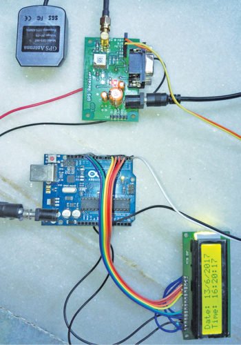
The circuit need not be assembled on a PCB. Connect the circuit using external header jumpers between Arduino Uno, LCD1 and SIM28M GPS receiver module. Connect a 9V power supply adaptor each to the SIM28M GPS receiver module and Arduino. Also connect ANT.1 to GPS1 module. Place the unit with LCD1 at a suitable location.
The author’s prototype is shown in Fig. 4.
Read More Detail:GPS Clock using Arduino
- What microcontroller board is used in this project?
The project uses an Arduino Uno R3 based on the AVR ATmega328 microcontroller. - How does the system extract time and date?
It extracts the time and date from the $GPRMC string received from the GPS module. - What baud rate is used for communication?
Both the GPS module and the Arduino are configured to operate at a 9600bps baud rate. - Can this clock be built on a PCB?
No, the circuit can be assembled using external header jumpers without needing a PCB. - Which specific string is processed by the Arduino program?
The Arduino program specifically processes the $GPRMC string which contains the time and date. - How do you view the raw GPS output before connecting the microcontroller?
You remove the ATmega328 chip from the board and open the Serial Monitor in Arduino IDE. - What software environment is required to compile the code?
Arduino IDE version 1.6.4 is used to compile and upload the sketch. - Are external header files required for the programming?
No, external header files are not required as the necessary libraries are included in the standard environment.