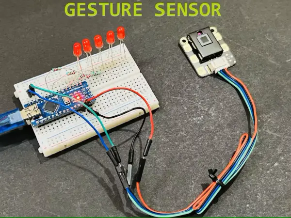
Summary of Gesture Sensor Control Using Arduino
This project uses the DFRobot Gravity gesture and touch sensor with an Arduino Nano to detect 7 gestures and a 5-way touch pad, driving LEDs (and optional OLED/buzzer) via serial (UART) communication. It supports adjustable detection distance (0–30 cm), auto-sleep/wake, and configurable functions; performance is best indoors and when hand covers the sensor. Code examples and PCB/shield suggestions are provided for a simple LED-demo and expanded builds.
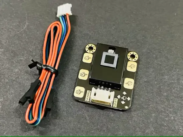
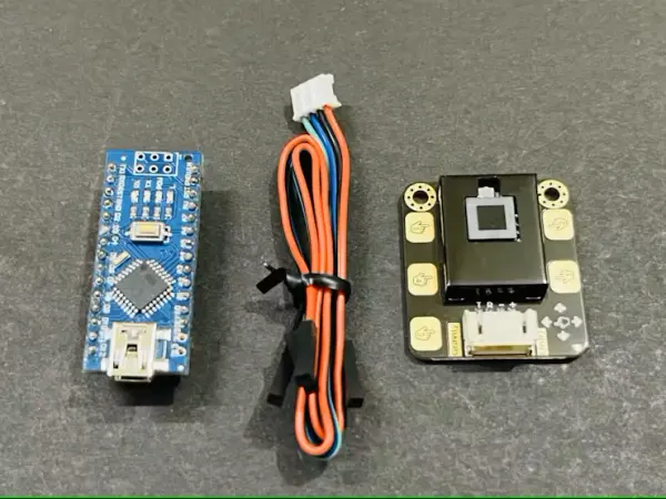
Parts used in the Gravity Gesture and Touch Sensor Project:
- DFRobot Gravity Gesture Touch sensor module
- Arduino Nano
- 5mm red LEDs (x4 or x5 as used)
- 220 ohm resistor
- Breadboard
- Custom PCB / Arduino Nano shield (optional)
- 128x64 OLED (optional on shield)
- Buzzer (optional on shield)
- Male headers
- 5V external power supply (1A suggested) or 9–12V barrel jack for shield
The DF Robot Gravity sensor now combines gesture controls and touch switches, offering an expanded array of combinations to manage the ON/OFF switch.
Narrative
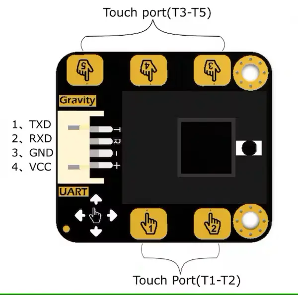
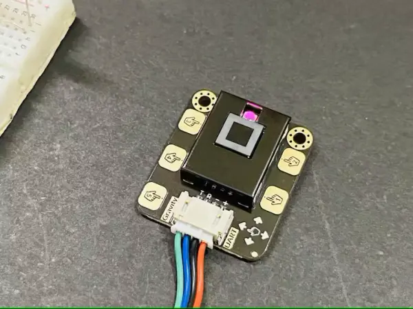
This sensor module combines gesture recognition and touch detection capabilities into a single unit, offering an adaptable detection range spanning from 0 to 30cm. When linked to your microcontroller, it is capable of identifying a 5-way touch signal and recognizing 7 distinct gestures: leftward movement, rightward movement, forward motion, backward motion, upward pull, downward pull, and pulling and removing.
Furthermore, the sensor is furnished with an auto-sleep and wake-up feature. The module incorporates a gesture recognition algorithm and delivers straightforward and dependable data output. Employ the sensor for direct communication with higher-level computers or microcontrollers such as Arduino and Raspberry Pi through a serial port connection.
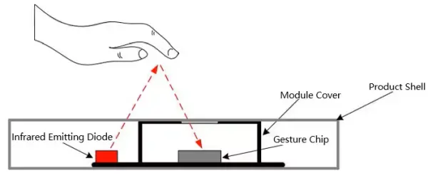
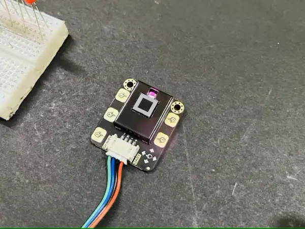
Operating based on the principle of infrared detection, this mechanism monitors hand motion through an infrared LED and sensing system. The infrared light interacts with the hand, then proceeds to the sensing unit for accurate interpretation. Infrared (IR) light falls within the invisible spectrum, and the sensor utilized in this process exhibits high selectivity. However, it’s worth noting that IR is also present in sunlight, which is why the sensor’s effectiveness is somewhat diminished when used outdoors.
Application of gesture and touch:
The sensor features a built-in 5-way touch pad that can be utilized for direct touch detection. Alternatively, you have the option to extend the touch pad using wires to seamlessly integrate it into your specific application. The external shield of the sensor not only preserves the benefits of the Gravity series but also enhances the sensor’s durability. This versatile sensor is ideal for creating a smart lamp, crafting a DIY intelligent car, or incorporating into interactive projects that demand gesture recognition capabilities.
Features:
- Power Supply: 3.3V – 6V (recommend 5V)
- Output Voltage: 0 – 3.3V
- Operating Current: about 56.3mA
- Sleep Mode Current: about 40uA
- Output: TTL serial port
- Serial Protocol Format: 9600 band rate; 8 data bits, no parity bit, 1 stop bit
Note:
Under intense sunlight conditions, the module’s operational principle may lead to irregularities.
Upon powering down, the sensor will undergo automatic initialization, rendering the prior configuration ineffective.
While continuously transmitting bytes, it’s essential to maintain a minimum time interval of 200 microseconds between the conclusion of the previous byte and the commencement of the subsequent one. The sensor is exclusively capable of data reception/transmission in its operational state; however, during data processing, the sensor must be in a non-operational state. Consequently, if an object is present over the sensor during data reception/transmission, it’s necessary to relocate it to finalize the subsequent configurations.
Normal Settings and functions:
- Default function when powered on: no sleep, 5-way touch, detecting height: 15cm.
- The default detecting height is 15cm, higher height detection needs to be set by yourself.
- Keep a normal speed when gesticulating to let the sensor better understand your gesture
Code functions:
1) Adjust the sensing height (initially set at 20cm upon power-up).
Example: DFGT.setGestureDistance(20);---Unit(cm) Max height: 30cm2) Enable sleep mode or activate auto-sleep (sleep mode is inactive upon power-up).
Example: DFGT.setSleep(4);---unit(s)3) Enable gesture sensing (all seven gestures are recognizable upon power-up).
Example(1) DFGT.enableFunction(DFGT_FUN_ALL);---enable all gestures sensing fuction

Example(2) DFGT.disableFunction(DFGT_FUN_RIGHT | DFGT_FUN_LEFT);---disable sensing function of part gestures

Example(3) DFGT.enableFunction(DFGT_FUN_RIGHT | DFGT_FUN_LEFT);---enable sensing function of part gestures
Components Required:
- Led 5mm red
- 220ohms resistor
- ARDUINO NANO
- Breadboard
- Custom PCB design
Circuit diagram:
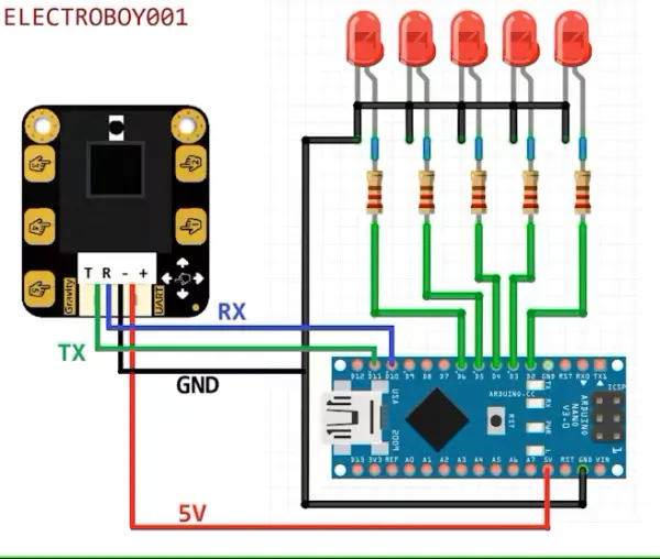
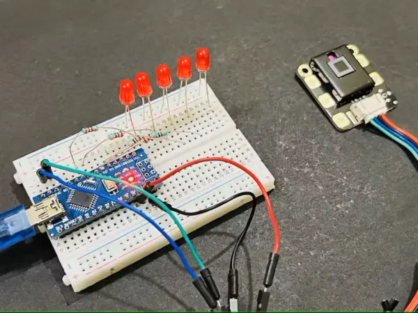
The digital pins of the Arduino NANO are linked to the four red LEDs. The gravity sensor interfaces with digital pins 10 and 11. The sensor’s Rx is connected to the Tx pin, while the sensor’s Tx is connected to the Rx, as defined in the Arduino’s software serial configuration. The LEDs are assigned distinct roles corresponding to actions and functions outlined in the Arduino program. Establishing the connections is straightforward. To energize the circuit, a 5V external power supply with a current rating of 1 amp can be employed.
Whenever working on a project involving this type of sensor, it’s possible to create a customized PCB. My recommendation is to utilize the PCB manufacturing services offered by JLCPCB, known for delivering excellent services at competitive prices. You can explore their offerings, such as obtaining five units of a 2-layer PCB for just $2, and their SMT assembly starting from a mere $8.
Simple testing code:
The sensor’s readings are displayed on the serial monitor via the Arduino’s serial port (UART), and the gravity sensor is compatible with the UART interface as well. This is why the Arduino code employs software serial, with the RX pin designated as D10 and the TX pin as D11.
// Modified by Sagar saini

#include "DFRobot_Gesture_Touch.h"

#ifdef __AVR__
  SoftwareSerial    mySerial(/*RX*/10, /*TX*/11);
#elif defined ESP_PLATFORM
// ESP32:IO16 <--> TX:sensor
// ESP32:IO17 <--> RX:sensor
HardwareSerial mySerial(1);
#endif

// init sensor object, request write and read function
DFRobot_Gesture_Touch   DFGT(&mySerial);

int led_1 = 2;
int led_2 = 3;
int led_3 = 4;
int led_4 = 5;
int led_5 = 6;

void setup()
{
  Serial.begin(115200);
  pinMode(led_1, OUTPUT);
  pinMode(led_2, OUTPUT);
  pinMode(led_3, OUTPUT);
  pinMode(led_4, OUTPUT);
  pinMode(led_5, OUTPUT);

  // suggest default value
  DFGT.setGestureDistance(20);

  // enable all functions
  DFGT.enableFunction(DFGT_FUN_ALL);

  // disable function test
  //DFGT.disableFunction(DFGT_FUN_RIGHT | DFGT_FUN_LEFT);

  // enable function test
  // DFGT.enableFunction(DFGT_FUN_RIGHT | DFGT_FUN_LEFT);

  // set auto sleep time out, in sleep mode, something approach will wake it up
  // DFGT.setSleep(4);

  Serial.println("simple Gesture!");
}

void loop()
{
  // get an event that data saved in serial buffer
  int8_t rslt = DFGT.getAnEvent();

  if(rslt != DF_ERR)
  {
    // disable auto sleep
    // DFGT.setSleep(DFGT_SLEEP_DISABLE);
    switch(rslt)
    {
      case DFGT_EVT_BACK:
        Serial.println("get event back");
        digitalWrite(led_1, HIGH);
        break;
      case DFGT_EVT_FORWARD:
        Serial.println("get event forward");
        digitalWrite(led_1, LOW);
        break;
      case DFGT_EVT_RIGHT:
        Serial.println("get event right");
        digitalWrite(led_2, HIGH);
        break;
      case DFGT_EVT_LEFT:
        Serial.println("get event left");
        digitalWrite(led_2, LOW);
        break;
      case DFGT_EVT_PULLUP:
        Serial.println("get event pull up");
        all_on();
        break;
      case DFGT_EVT_PULLDOWN:
        Serial.println("get event pull down");
        all_off();
        break;
      case DFGT_EVT_PULLREMOVE:
        Serial.println("get event pull and remove");
        all_off();
        break;
      case DFGT_EVT_TOUCH1:
        Serial.println("get event touch1");
        digitalWrite(led_1, HIGH);
        break;
      case DFGT_EVT_TOUCH2:
        Serial.println("get event touch2");
        digitalWrite(led_2, HIGH);
        break;
      case DFGT_EVT_TOUCH3:
        Serial.println("get event touch3");
        digitalWrite(led_3, HIGH);
        break;
      case DFGT_EVT_TOUCH4:
        Serial.println("get event touch4");
        digitalWrite(led_4, HIGH);
        break;
      case DFGT_EVT_TOUCH5:
        Serial.println("get event touch5");
        digitalWrite(led_5, HIGH);
        break;
    }
  }
}

void all_on(){
  digitalWrite(led_1, HIGH); // write your own functions to control digital outputs
  digitalWrite(led_2, HIGH); // or to do something else with the gestures
  digitalWrite(led_3, HIGH); // now it is upto you how you play
  digitalWrite(led_4, HIGH);
  digitalWrite(led_5, HIGH);
  delay(100);
}

void all_off(){
  digitalWrite(led_1, LOW);
  digitalWrite(led_2, LOW);
  digitalWrite(led_3, LOW);
  digitalWrite(led_4, LOW);
  digitalWrite(led_5, LOW);
  delay(100);
}
Functions used:
I’ve initialized all functions to enable the activation of various movements and touch actions. To achieve this, I’ve incorporated an external function within the Arduino sketch that toggles the Red LEDs linked to the Digital I/O pins.
PCB designs:
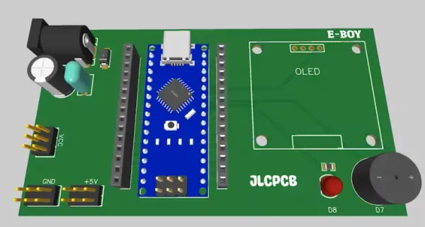
I crafted a shield for this uncomplicated project, a method I find to be quite effective. The shield incorporates an Arduino Nano, securely soldered onto the board, with convenient male headers in proximity for establishing connections. Displaying data is facilitated by an integrated 128×64 OLED, and for digital output purposes, a buzzer and LED are included. The power aspect is well-optimized; simply provide power through a barrel jack with a voltage range of 9 to 12 volts.
Testing:
I conducted testing on the sensor with a 20cm height configuration, excluding sleep mode, and with all functions activated. The sensor exhibited flawless performance under room lighting conditions. However, I’m less certain about its performance in daylight. While attempting to identify left-right gestures, the accuracy was somewhat compromised.
The most optimal response I observed occurred when utilizing the pull up, pull down, and pull and remove functions under sunlight conditions. The sensor’s performance was notably satisfactory in these scenarios since the hand covers the sensor in these three cases. The touch responsiveness is exceptional, surpassing that of other touch sensors, and the response time is remarkably swift.
The touch wires have the flexibility to be extended, and it’s possible to create an external copper pad tailored for various applications. I’ve developed a basic code snippet solely for toggling LEDs by manipulating the digital outputs of the Arduino. However, you have the freedom to craft your own functions to achieve different objectives. The ball is now in your court, allowing you to explore how you want to engage with it.
Code
// Modified by Sagar saini

#include "DFRobot_Gesture_Touch.h"

#ifdef __AVR__
  SoftwareSerial    mySerial(/*RX*/10, /*TX*/11);
#elif defined ESP_PLATFORM
// ESP32:IO16 <--> TX:sensor
// ESP32:IO17 <--> RX:sensor
HardwareSerial mySerial(1);
#endif

// init sensor object, request write and read function
DFRobot_Gesture_Touch   DFGT(&mySerial);

int led_1 = 2;
int led_2 = 3;
int led_3 = 4;
int led_4 = 5;
int led_5 = 6;

void setup()
{
  Serial.begin(115200);
  pinMode(led_1, OUTPUT);
  pinMode(led_2, OUTPUT);
  pinMode(led_3, OUTPUT);
  pinMode(led_4, OUTPUT);
  pinMode(led_5, OUTPUT);

  // suggest default value
  DFGT.setGestureDistance(20);

  // enable all functions
  DFGT.enableFunction(DFGT_FUN_ALL);

  // disable function test
  //DFGT.disableFunction(DFGT_FUN_RIGHT | DFGT_FUN_LEFT);

  // enable function test
  // DFGT.enableFunction(DFGT_FUN_RIGHT | DFGT_FUN_LEFT);

  // set auto sleep time out, in sleep mode, something
approach will wake it up
  // DFGT.setSleep(4);

  Serial.println("simple Gesture!");
}

void loop()
{
  // get an event that data saved in serial buffer
  int8_t rslt = DFGT.getAnEvent();

  if(rslt != DF_ERR)
  {
    // disable auto sleep
    // DFGT.setSleep(DFGT_SLEEP_DISABLE);
    switch(rslt)
    {
      case DFGT_EVT_BACK:
        Serial.println("get event back");
        digitalWrite(led_1, HIGH);
        break;
      case DFGT_EVT_FORWARD:
        Serial.println("get event forward");
        digitalWrite(led_1, LOW);
        break;
      case DFGT_EVT_RIGHT:
        Serial.println("get event right");
        digitalWrite(led_2, HIGH);
        break;
      case DFGT_EVT_LEFT:
        Serial.println("get event left");
        digitalWrite(led_2, LOW);
        break;
      case DFGT_EVT_PULLUP:
        Serial.println("get event pull up");
        all_on();
        break;
      case DFGT_EVT_PULLDOWN:
        Serial.println("get event pull down");
        all_off();
        break;
      case DFGT_EVT_PULLREMOVE:
        Serial.println("get event pull and remove");
        all_off();
        break;
      case DFGT_EVT_TOUCH1:
        Serial.println("get event touch1");
        digitalWrite(led_1, HIGH);
        break;
      case DFGT_EVT_TOUCH2:
        Serial.println("get event touch2");
        digitalWrite(led_2, HIGH);
        break;
      case DFGT_EVT_TOUCH3:
        Serial.println("get event touch3");
        digitalWrite(led_3, HIGH);
        break;
      case DFGT_EVT_TOUCH4:
        Serial.println("get event touch4");
        digitalWrite(led_4, HIGH);
        break;
      case DFGT_EVT_TOUCH5:
        Serial.println("get event touch5");
        digitalWrite(led_5, HIGH);
        break;
    }
  }
}

void all_on(){
  digitalWrite(led_1, HIGH);
  digitalWrite(led_2, HIGH);
  digitalWrite(led_3, HIGH);
  digitalWrite(led_4, HIGH);
  digitalWrite(led_5, HIGH);
  delay(100);
}

void all_off(){
  digitalWrite(led_1, LOW);
  digitalWrite(led_2, LOW);
  digitalWrite(led_3, LOW);
  digitalWrite(led_4, LOW);
  digitalWrite(led_5, LOW);
  delay(100);
}
- What gestures does the sensor recognize?
The sensor recognizes left, right, forward, backward, pull up, pull down, and pull and remove gestures. - What touch inputs does the module provide?
It provides a built-in 5-way touch pad and the touch pad can be extended with wires or an external copper pad. - What is the detection range of the sensor?
The detection range is adjustable from 0 to 30 cm with a default detecting height of 15 cm (example code sets 20 cm). - What power supply does the sensor require?
Power supply is 3.3V to 6V (5V recommended); example circuit uses a 5V supply with 1A capacity. - How does the sensor communicate with a microcontroller?
The sensor outputs via a TTL serial port using UART at 9600 baud, 8N1, and the example uses SoftwareSerial on Arduino pins D10 (RX) and D11 (TX). - Does the sensor work outdoors in sunlight?
The sensor is less effective in intense sunlight because it uses infrared detection and sunlight contains IR, which can cause irregularities. - Can the sensor enter sleep mode?
Yes, the sensor supports auto-sleep and wake-up; sleep mode is disabled by default but can be set with DFGT.setSleep(seconds). - What is the sensor's current consumption?
Operating current is about 56.3 mA and sleep mode current is about 40 µA, as stated in the features. - How should bytes be transmitted to the sensor?
Maintain at least 200 microseconds between the end of the previous byte and the start of the next while continuously transmitting bytes. - What should be done if an object covers the sensor during data transmission?
If an object is over the sensor during data reception/transmission, you must move it away to finalize subsequent configurations because the sensor must be non-operational during data processing.