If you and a friend have ever wondered who is better at flexing a flex sensor just right, you can now settle it with Flex-it. Flex-it is my second original project using the SparkFun RedBoard.
Flex-It: The Flex Sensor Game
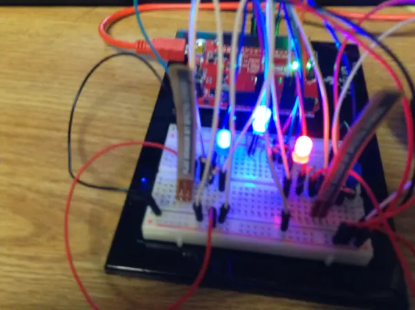
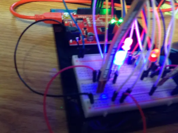
The Flex-It is a small game for two players, each equipped with a flex sensor connected to their own LED (red or blue). As you flex the sensor, your LED will either brighten or dim. The goal is to dim your light below a certain point. The first player to achieve this wins, locking both the sensors and LEDs. The RGB LED will then light up with the winner’s color—blue if the blue player wins and red if the red player wins. To reset the game, press the button, causing the RGB LED to flash green. Players can keep track of their score by opening the serial display before starting the game. Note that opening the serial display after a few rounds will reset the game, losing records of previous wins.
(My apologizes about the difficulty to read the computer screen. It simply displays the score after each light has been lit up.)
Development of Flex-It
The assignment required us to use analog inputs and outputs. After experimenting with a flex sensor in class and using it with a motor, I found it quite interesting and decided to explore it further. I liked the idea of having two players compete to turn off LEDs. I started sketching this concept and then added an RGB LED to clearly indicate the winner. Soon after, I decided to include a button to easily reset the game, a feature that proved invaluable when I realized that resetting the entire RedBoard to restart the game was unnecessarily cumbersome.
Overcoming Challenges in Flex-It
Some of my biggest challenges came with the wiring. I made a few mistakes connecting resistors and wires to the appropriate parts. For example, I accidentally wired the push button incorrectly, causing the five volts to run in the same row as the wire attached to the pin, resulting in incorrect readings. I also struggled to set the appropriate range for the flex sensors and LED brightness. While this range could be adjusted more accurately with greater skill and practice, I feel I got it as close as possible. Additionally, it took me a while to get the code for the push button working correctly, and I needed my instructor’s help to properly use the return() function. Finally, I decided to track the score and display it on the Serial display using Serial.println();. With these challenges addressed, I completed the project, as seen below.
Building Your Own Flex-It
If you’d like to build your own Flex-It, read below for schematics, parts, and the code.
Parts Needed:
- (1) SparkFun Redboard or Arduino Uno
- (1) Blue LED
- (1) Red LED
- (1) RGB LED
- (2) Flex Sensors
- (5) 330 Ohm Resistors
- (3) 10K Ohm Resistors
- (1) Push Button
- (Approx. 19) Wires
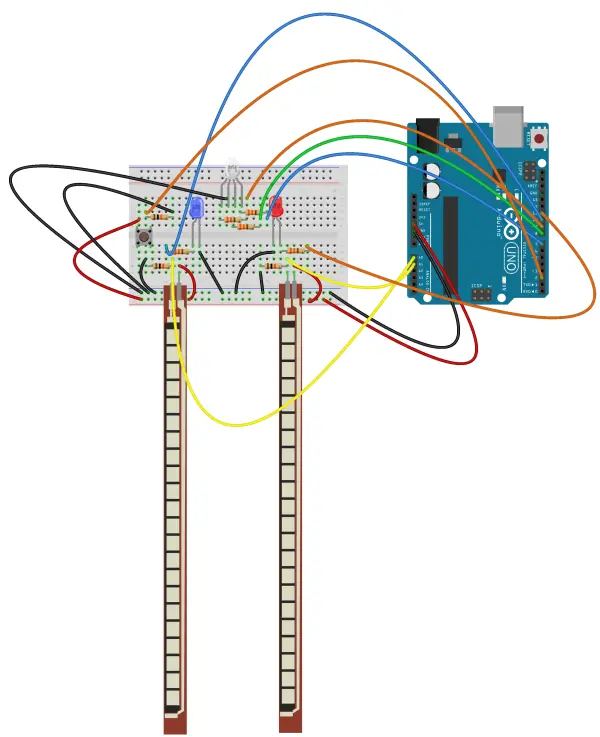
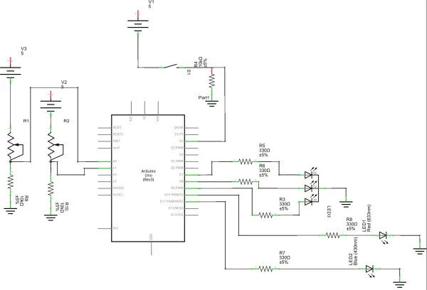
The basic schematic and sketch can be seen below:
Connecting Components for Sensor and LEDs
To set up your circuit as described:
- Flex Sensor Setup:
- Connect one end of a wire to the 5 volts supply.
- Attach the other end of the wire to the side of the flex sensor that leads to the thin line.
- Resistor and Analog Output Connection:
- From the opposite side of the flex sensor, connect a 10K Ohm resistor to ground.
- Attach another wire from this side to one of the analog output pins (e.g., A0 or A1).
- LED Connections:
- Blue and Red LEDs:
- Connect the negative ends of the blue and red LEDs to ground.
- Run a wire from pin 11 through a resistor to the positive side of the blue LED.
- Similarly, connect the red LED’s positive side to pin 10 through a resistor.
- Use any PWM-capable digital pins for these connections (marked by a tilde (~)).
- Blue and Red LEDs:
- RGB LED Connection:
- Connect the red, green, and blue pins of the RGB LED to any digital output pins (e.g., 9, 8, and 7 respectively).
- Button Setup:
- Apply 5 volts to one row of the button.
- Connect a wire from the button to a digital pin.
- Place a resistor between this digital pin and ground.
This setup allows you to effectively interface the flex sensor, LEDs, and button with your microcontroller or Arduino board. Adjust pin numbers as needed based on your specific hardware configuration.
Provided Code
Below is the code I utilized. Please feel free to make any necessary adjustments.
/* Flex-itThe game should work that two players flex the sensorswith the intent of dimming the light to a certain point.Whoever succeeds first the RGB LED will light up that color, i.e.if blue wins then the RGB LED will light up blue.If the push button is pressed it should reset the circuit soit can be played again. And if the Serial screen is opened it will keeptrack of the score, though it must be started before the two players begin.*///Set up variablesconst int blue = 11;const int red = 10;const int RGBred = 9;const int RGBgreen = 8;const int RGBblue = 7;const int pushButton = 2;const int minRed = 15;const int maxRed = 330;const int minBlue = 15;const int maxBlue = 345;int counterRed = 0;int counterBlue = 0;void setup() { // set up our inputs pinMode(pushButton, INPUT); //set up our outputs pinMode(RGBred, OUTPUT); pinMode(RGBgreen, OUTPUT); pinMode(RGBblue, OUTPUT); Serial.begin(9600);}void loop() { digitalWrite(RGBgreen, LOW); int redSensor; // define a variable for the red light's sensor int blueSensor; // define a variable for the blue light's sensor int redMap; // map the range of the red sensor to fit analog values better int blueMap; // map the range of the blue sensor to fit analog values better redSensor = analogRead(A1); blueSensor = analogRead(A0); //have the values of the sensors sent to our computer //so that we can set our output to the most appropriate values //Serial.println("redsensor:"); //Serial.println(redSensor); //Serial.println("redmapping"); //Serial.println("bluesensor:"); //Serial.println(blueSensor); //delay(1000); //These were used for debugging and are limited to comments // so the final score can be displayed with less clutter. //constrain the results of our sensor to the sweet //spot of the flex senors redSensor = constrain(redSensor, minRed, maxRed); blueSensor = constrain(blueSensor, minBlue, maxBlue); //map the values of the sensor to be more accurate //with analogWrite redSensor = map(redSensor, minRed, maxRed, 0, 255); blueSensor = map(blueSensor, minBlue, maxBlue, 0, 255); analogWrite(red, redSensor); analogWrite(blue, blueSensor); int buttonState; // set up a variable to use for our reset button while ((redSensor < minRed)) { //indicates that red won digitalWrite(RGBred, HIGH); analogWrite(blue, 255); buttonState = digitalRead(pushButton); //check the value of the push button if (buttonState == HIGH) { //resets the game analogWrite(red, 0); digitalWrite(RGBred, LOW); analogWrite(blue, 0); digitalWrite(RGBblue, LOW); digitalWrite(RGBgreen, HIGH); counterRed++; // keeps track of how many times red has won. Serial.println("Red Wins:"); Serial.println(counterRed); Serial.println("Blue Wins:"); Serial.println(counterBlue); delay(1000); return (loop()); Serial.println("it works"); // message to ensure the switch work } } while ((blueSensor < minBlue)) { //indicates that blue won digitalWrite(RGBblue, HIGH); analogWrite(red, 255); buttonState = digitalRead(pushButton); //check the value of the button if (buttonState == HIGH) { //resets the game analogWrite(red, 0); digitalWrite(RGBred, LOW); analogWrite(blue, 0); digitalWrite(RGBblue, LOW); digitalWrite(RGBgreen, HIGH); counterBlue++; // keeps track of how many times blue has won. Serial.println("Red Wins:"); Serial.println(counterRed); Serial.println("Blue Wins:"); Serial.println(counterBlue); delay(1000); return (loop()); Serial.println("it works"); // message to ensure the switch worked } }}Code Explanation and Project Suggestions
The code is relatively straightforward. Most of the points are clarified in the comments, but I’ll summarize the main aspects here. Essentially, the code initializes variables and reads analog input values directly. Instead of specifying them as inputs at the start, we read and find a usable range. This range constrains the values we read and maps them to a relative range for our analog outputs. The code continuously checks these values until either the red or blue analog output reads below the minimum, triggering the RGB LED to light up and halting analog value calculations. It also increments the appropriate scorer’s points. Additionally, the code monitors the push button status; if it reads high, the loop restarts until power is cut.
The project could expand to any analog input, like a potentiometer. Using a larger breadboard would reduce clutter and accommodate features like an LCD score display instead of relying on the computer’s Serial monitor. Space constraints prevented integrating this; adjusting maximum and minimum values might enhance precision. Occasional issues arise where flex sensors dislodge while being flexed, possibly due to user error; improving pin grip would help.
Follow this link for complete project: Flex-It: The Ultimate Flex Sensor Showdown


