
Hi guys, we will make an interesting project in this project. We will try to make a flame by snapping our finger.Let’s get started on the project.
Step 1: Video Tutorial
You can see the project step by step with this video tutorial. For the first time, I will explain this project by speaking. I don’t speak English very well, so you can turn on the subtitle for this video. I will be better in the next projects. Your support is very important for me.
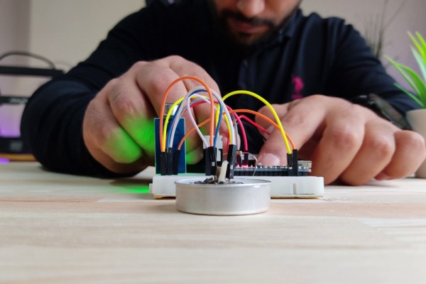
Step 2: Create a Prototype (Connections)
First, let’s create a prototype. I will use Arduino Nano for this project. You can use any Arduino model you want. The source codes will work on all of them.
Parts Required for Prototype:
1x Arduino Nano V3 – http://bit.ly/2MHVDYi
1x Sound Sensor Module – https://bit.ly/3fuZoP7
1x IRFZ44N Mosfet – https://bit.ly/3fthnFF
2x 3.7v Battery 18650 – https://bit.ly/2ECGb01
1x Battery Holder 18650 – https://bit.ly/30cqwMJ
1x Breadboard – http://bit.ly/30ckFoc
Resistor Pack – http://bit.ly/2lJhi8Z
Jumper Wires – http://bit.ly/2MtyZCX
Matches and Candles
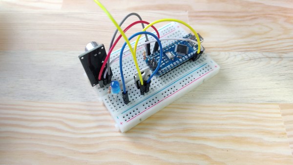
- Let’s put the Arduino Nano on a breadboard. Next, let’s plug in the sound sensor.
- We need a Mosfet for switching and power balancing. Also, we need a resistor to use with Mosfet.
- Next, I’ll use an LED to adjust and see the sensitivity of the sound sensor. Actually, LED is just like a flame trigger. Of course, I add a resistor that I will use only for LED.
Yes, we’ve completed all the components. Let’s start making connections.
Sound Sensor:
- Sound sensor VCC to Arduino +5V
- Sound sensor GND to Arduino GND
- Sound sensor OUT to Arduino Digital 10
Mosfet & LED:
- Mosfet Pin 1 (Gate leg) to Arduino Digital 9
- Mosfet Pin 1 to 10K Resistor
- 10K Resistor other leg to Arduino GND
- Mosfet Pin 2 (Drain leg) to LED (-)
- LED (+) to 220 Ohm Resistor
- 220 Ohm Resistor other leg to Arduino VIN
We’ve completed the connections, now let’s take a closer look at the source code.
Step 3: Source Code

- The object defined as FLAME in the source code is the LED component. We only used the LED component to see if it was triggering. It is connected to pin 9 of the arduino.
- The LED object is the built-in LED on the Arduino. We used it to observe the arduino react. The built-in LED is connected to pin 13 of the Arduino.
- The sound sensor is connected to pin 10 of Arduino Nun. When it detects sound, it triggers the FLAME and LED object and sets it to HIGH. Continues to be HIGH for 10 seconds, then set to LOW if there is no sound.
You can get the source code from the link below:
https://github.com/MertArduino/Flame-by-Snapping-Finger/blob/main/FlameBySnapping.ino
Step 4: Adjust the Sensitivity of the Sound Sensor
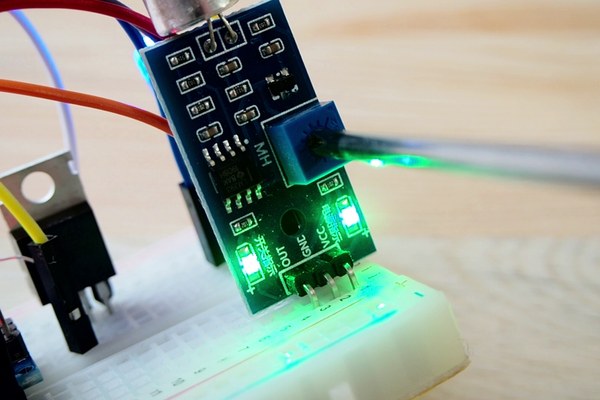
Now adjust the sensitivity of the sound sensor, the LED should light when we snap our finger. By the way, I will use another sound module because this sound sensor is broken. What I want is to set the sound sensor not to be activated with any sound. We turn the pot on the sound sensor with the help of a screwdriver. Adjust the sensitivity of the sound sensor to activate it by snapping your finger.
Step 5: Use a Wire to Trigger the Flame
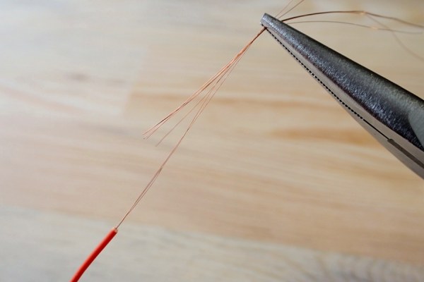
Now instead of the LED, we will use wire to activate the flame.
- Now let’s remove a wire from the any jumper wire.
- Let’s check the flammability of this wire with any battery.
- Now we remove the LED and connect 2 pcs jumper wires instead of LED legs.
Step 6: Prepare Gunpowder
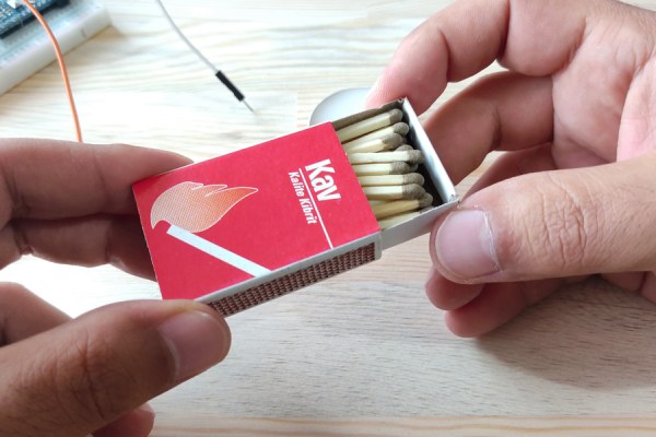
The system is ready to work, now let’s prepare some gunpowder. So we can make a cool and magical project. I will use matches to get gunpowder. Also use a candle for its flame. Finally, I connect the flame wire to the end of the jumper wires.
Step 7: Showtime! But Safety First!
I will connect a 2 pcs 18650 (7.4v) battery to run the system.
- Battery (+) to Arduino VIN
- Battery (-) to Arduino GND
Everything is ready, but safety first! Please wear safety goggles and I recommend that you have a fire extinguisher handy just in case.
If you are ready, all you have to do for the show is to SNAP your FINGER.
Step 8: PCB Design & Schematic
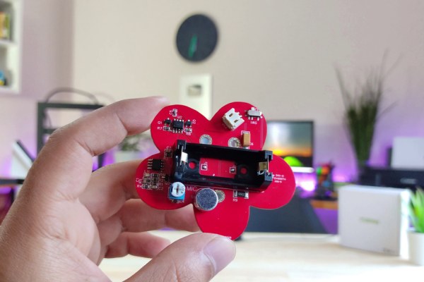
The prototype works fine, but it can be difficult to use this project with so many wires, so I designed a PCB for this project. First of all, thank you to PCBWay for sponsoring this project. New members first order & Low Price for PCB Stencil at https://www.pcbway.com/
Meanwhile, PCBWay yearly-end Big Sale will start. For more details check PCBWay XMAS Activity page:
December Shopping Festival is finally comes – https://www.pcbway.com/activity/xmas2020sales.html
You can find the schematic and gerber file for this PCB design from the link below:
Get the Gerber File & Schematic:https://www.pcbway.com/project/shareproject/Flame_by_Snapping_Finger.html
To have this PCB, all you have to do is upload the gerber file to the PCBWay web page.
I wanted this circuit board to be minimal, so I chose to use ATtiny13 microcontroller. How to upload source code to the ATtiny microcontroller? I’ve found a shield that makes programming easier. For more information about ATtiny Bootloader Shield: https://youtu.be/PbrSABWPlBg
Step 9: The Project Is Ready

All steps are the same as for an arduino prototype, I’ll use this candle as the difference. I hope you enjoyed the project. Thanks for watching / reading and see you on the next project.
Source: Flame the Candle by Snapping Your Finger