Summary of Fast analog isolation with linear optocouplers
Analog optocoupler HCNR201/200 provides low-cost, high-linearity analog isolation using a single LED and two closely matched photodiodes (PD1 input, PD2 output). Monitoring PD1 stabilizes LED output and, with appropriate circuitry, yields stable gain, low nonlinearity, tight transfer gain matching, low temperature coefficient, and wide bandwidth (DC to >1 MHz). Packaged in 400 mil DIP8 and IEC60747-5-5 certified, the parts suit motor drives, SMPS feedback, transducers, and current loops. A discrete-transistor implementation can reach ~1.5 MHz bandwidth with VOUT/VIN = R2/R1.
Parts used in the HCNR201/200 Analog Optocoupler Implementation:
- HCNR201 or HCNR200 analog optocoupler (single LED with two photodiodes PD1 and PD2)
- LED (internal to HCNR201/200)
- Photodiode PD1 (input photodiode, internal)
- Photodiode PD2 (output photodiode, internal)
- Discrete transistors (external, for the high-speed low-cost implementation)
- Resistors R1 and R2 (set transfer function VOUT/VIN = R2/R1)
- 400 mil DIP8 widebody package (package type for HCNR201/200)
Introduction
Analog isolation is still widely used in motor drives, power monitoring, etc whereby applications typically use inexpensive analog voltage control for speed, intensity or other adjustments.
The HCNR201/200 analog optocoupler is commonly added to isolate the analog signal in the front end module of an application circuitry. The optocoupler will be placed between the analog input and the A/D converter to provide isolation of the analog input from the mixed signal ADC and other digital circuitries. The HCNR201/200 is an excellent solution for many of the analog isolation problems.
Key Features and Specifications
The HCNR201/200 analog optocoupler consist of a single LED with two photodiodes, PD1 and PD2 as shown in the diagram below. The two photodiodes are closely matched, with PD1 on the input side and the PD2 on the output side of the application circuitry. The output current of the photodiode is linearly related to the light output of the LED. Having an input photodiode, PD1 allows a direct monitoring of the LED condition, hence stabilizing the light output of the LED. With close matching of the two photodiodes and with suitable application circuitry, HCNR201/200 can achieve high linearity and stable gain characteristics. The advantage of using HCNR201/200 lies in its flexibility of operating in a wide variety of different modes, such as in unipolar/bipolar, ac/dc and inverting/non-inverting configurations. Both HCNR201 and HCNR200 are housed in 400mil DIP8 widebody package.
The key features and characteristics of HCNR201/200 High Linearity Analog Optocoupler are as follow:
- Low Cost Analog Isolation, High Linearity, Flexible design with ease of accessing the two photodiodes
- Tighter K3 (IPD2/IPD1) Transfer Gain – Current flowing in output photodiode PD2 vs current flowing in the input photodiode PD1, this indicate how closely match are the two photodiodes
- Low Nonlinearity – Maximum deviation (in %) of the full scale output of a “best fit” straight line drawn from the plot Ipd2 vs Ipd1 from 5nA to 50μA. Straight line drawn is based on 11 point equally spaced from 5nA to 50μA. IPD2 error to best fit line is the deviation above and below the best fit line.
- Low Transfer Gain Temperature Coefficient – Gradient of K3 vs temperature plot. This indicate the transfer gain to temperature variations
- Wide Bandwidth : DC to > 1MHz
- IEC60747-5-5 certification for reinforced insulation with continuous working voltages at 1414 Vpeak and transient voltages of 8kVpeak for HCNR201/200
High Speed, Low Cost Implementation Using HCNR201/200
Avago had various circuitries that are designed to be used together with the HCNR201/200 to provide isolation and using them in a number of industrial applications, such as motor drives, switched mode power supplies, transducer, current loop, etc.
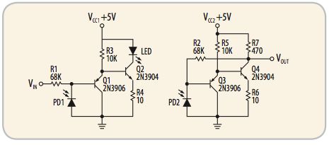
HCNR201/200 are used in different circuit configurations. Figure 1 illustrates a high speed, low cost implementation using HCNR201/200, achieving a high bandwidth of 1.5MHz with stable gain characteristics. For applications looking for high bandwidth, high speed and low cost solutions, this will be a suitable implementation as the circuitry consists of only discrete transistors (No op-amps). But it will have to tradeoff accuracy to achieve the high bandwidth and speed. This configuration is typically used in the feedback path of the switched mode power supplies. The transfer function is governed by:
VOUT/VIN = R2/R1
For more detail: Fast analog isolation with linear optocouplers
- What is the basic structure of the HCNR201/200 analog optocoupler?
It consists of a single LED and two closely matched photodiodes, PD1 on the input side and PD2 on the output side. - How does PD1 help the HCNR201/200 achieve stable performance?
PD1 monitors the LED condition directly, allowing stabilization of the LED light output. - What determines the transfer function in the high-speed discrete-transistor implementation?
The transfer function is VOUT/VIN = R2/R1, determined by resistors R1 and R2. - What bandwidth can be achieved with the high-speed, low-cost implementation?
The implementation can achieve a high bandwidth of about 1.5 MHz. - In which applications is the HCNR201/200 commonly used?
They are used in motor drives, switched mode power supplies, transducers, and current loop applications. - What are key performance characteristics of the HCNR201/200?
Key characteristics include high linearity, low nonlinearity, tight transfer gain matching (K3), low transfer gain temperature coefficient, and wide bandwidth. - What package and safety certification do HCNR201/200 have?
They are in a 400 mil DIP8 widebody package and have IEC60747-5-5 certification for reinforced insulation. - Does the high-speed implementation require op-amps?
No; the high-speed, low-cost implementation uses only discrete transistors and no op-amps.