This Instructable describes the construction of an electronic archery arrow spine tester. An arrow spine tester measures the stiffness of arrows. This helps an archer to construct arrows of uniform specifications which will shoot consistently.
Traditional arrow spine testers measure arrow stiffness, or spine, by hanging weights on the arrows and measuring the resultant sag of the arrows. This tester uses an alternative electronic approach. Commercial electronic arrow spine testers do exist but are extremely uncommon.
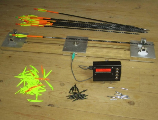
The electronic spine tester works by placing an arrow on the instrument, depressing the arrow with a finger, reading the forces on the arrow using load cells (also known as strain gauges), and converting these forces arithmetically using software on the Arduino into arrow spine values.
Supplies
Simple metalworking equipment
Simple electronics building equipment
An Arduino development environment (e.g. a PC)
Step 1: Project Overview
The project has mechanical, electronic and software aspects. Drawings and instructions are provided to allow the building of the instrument shown in the photographs. Additional notes are provided to allow the builder to modify the mechanics if desired.
Drawings are supplied for building the electronics on a breadboard or on Veroboard. A circuit diagram is also supplied to allow the builder to lay out their own circuit or modify it.
The software is provided complete and ready to use. If the builder chooses to investigate and/or modify the software they will see examples of:
- General Arduino programming in C++ using classes
- Interfacing to momentary switches including debouncing
- Interfacing to multiple load cells using HX711 interface boards (including calibration and accuracy improvement using constant averaging techniques)
- Interfacing to 2×16 displays using IC2 serial bus
- Storing data in EEPROM
- Putting the system into low power mode for power management
- Using interrupts to awaken from sleep mode
- Using the Arduino’s serial USB interface to provide debug functionality
The software is comprehensively commented to aid comprehension.
Step 2: What Is Arrow Spine?
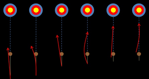
When an arrow is shot from a bow it does not remain straight; it in fact bends and oscillates from side to side. This oscillation can allow the arrow, if well suited to the bow, to ‘snake’ around it and fly straight to the target. If badly suited to the bow, the arrow will veer left or right or worst case strike the bow and bounce off randomly.
There are many factors which affect this arrow to bow matching but the main factor is arrow flexibility. This flexibility is usually referred to as arrow spine. Less flexible arrows are colloquially known as stiffer and more flexible arrows are colloquially known as weaker.
All other things being equal, arrows with the same spine will all shoot the same from a given bow. Being able to test the spine of an arrow or the shaft to be used to make one greatly simplifies the production of uniform arrows which are well suited to a particular bow.
Step 3: The History of Arrow Spine
From prehistory to the advent of firearms, arrows were manufactured were known as fletchers. A lifetime of experience of the feel of an arrow would let a fletcher intuitively match bow to arrow.
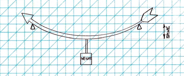
As archery became a hobby and as arrow manufacture became industrialised a standardised method of arrow spine measurement became desirable. Arrow spine measurements have had a number of standards and units over the years but they have traditionally revolved around the concept of placing an arrow on two supports a known distance apart (e.g. two nails) and hanging a known weight on the middle of the arrow. The deflection of the arrow is proportional to its flexibility. Variations in arrow spine methodologies and units mainly revolve around variations of the distance between the supports and the size of the weight.
The most used arrow spine testing specifications are laid down by the American Archery Trade Association (ATA) although there are many regional and historical variations. ATA’s specifications are heavily influenced by Easton who are America’s (and hence the world’s) biggest arrow manufacturer.
Step 4: Wooden Arrows
The first important standard was for wooden arrows and their matching to American Style ‘Longbows’ also known as American Flat Bows.
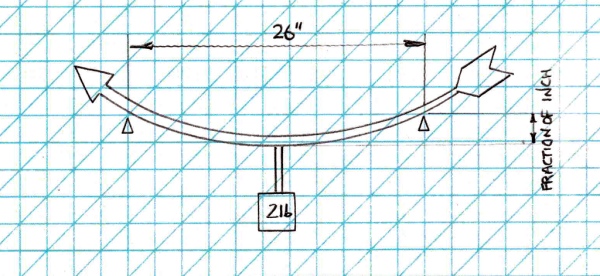
This standard specified arrow supports at 26 inch spacings and a 2lb weight hung in the middle.
The deflection of the arrow (in inches) was converted to the poundage of the notional bow that spine would suit by dividing 26 by that deflection. So a 1 inch deflection indicated a match to bow with a 26lb pull (26/1=26). A half inch deflection indicated a bow with a 52lb pull (26/0.5=52) and so on. For a basic American Flat Bow with a shooting shelf it tended to give good results, so it’s actually quite a cleverly chosen standard. It combined this with ease of understanding (A “24lb” arrow would likely shoot well from a 24lb American Flat Bow) and was simply applied to other bow styles (e.g. an English Longbow will tend to need arrows about 5lb weaker). It was clever and easy to understand so obviously it needed changed…
Step 5: Aluminium Arrows
Aluminium arrows are constructed from aluminium tubes which are specified by their dimensional properties. These dimensions a theoretical connection to the spine of the arrow but not an intuitive one.
This specification was introduced by the Easton company and it was their standard. It was not a standard that allowed arrow comparisons between different arrow manufacturing companies due to different materials specifications. It also was not a standard that allowed comparisons between Easton arrows of different vintages either as their materials changed. As materials improved the characteristics changed and Easton were faced with the choice of arrows with the same dimensions having different spines or maintaining the consistency of the arrow spines and making the ‘dimension’ numbers less related to physical arrow dimensions. This was a no-win scenario – Easton went with the latter option and the numbers quietly became ‘shaft codes’ with little relation to the true measurements of the arrow tubes. This wasn’t a great scenario either…
Step 6: A First Go at Something More Scientific
The first attempt at something more rational was using arrow supports at 26 inch spacings and a 2lb weight hung in the middle. The spine of an arrow, however, became the resultant deflection in thousandths of an inch rather than a guesstimate of the poundage of the bow that would shoot that arrow well.
So, a 500 spine arrow was an arrow that, when supported on 26 inch supports, and with a 2lb weight suspended from it at the middle, had a deflection of 500 thousandths of an inch. This standard allowed the reuse of existing arrow measuring equipment but was much more precise than older standards. Any 500 arrow matches any other 500 arrow and experience will let an archer know what spine number matches his bow. It’s not as easy or intuitive as older methods but it’s still relatively easy to explain. Better change it again then…
Step 7: Carbon and Carbon Aluminium Arrows
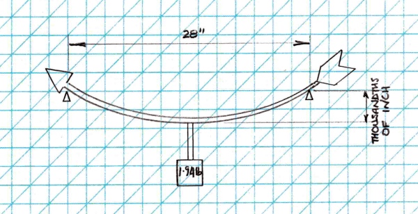
At around the same time that carbon and carbon/aluminium arrows started appearing, it was decided that it was time for a new standard. A 500 (for example) arrow spine would now be an arrow that deflects 500 thousandths of an inch when supported at centres of 28 inches with a weight of 1.94 lb suspended from the middle. This is the current ATA arrow spine specification.
Why the change from 26 to 28 inches? No idea. Why the change from a 2lb weight to a weight of 1.94lb? No idea. There is, however, an apocryphal story that someone at the Easton factory weighed their 2lb standard weight one day and discovered it to only weigh 1.94lb. To cover this up, they decided to change the standard to 1.94lb and changed the spacing from 26 inches to 28 inches as additional obfuscation. This is, however, an urban legend. Whatever the truth of the matter, this is the standard now used by most arrow shaft manufacturers.
Step 8: Cartel Are Different
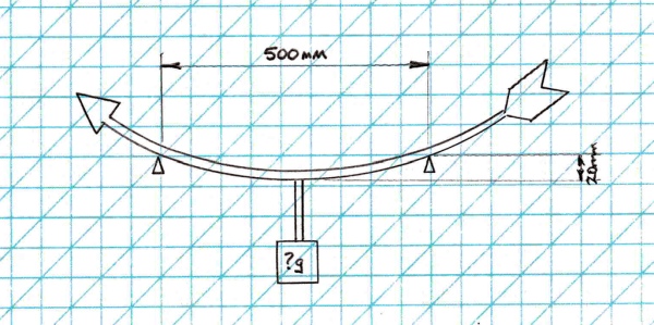
Cartel are a Korean archery company who, being outside of the American sphere of influence, do things differently. Cartel spines are the weight in grams required to deflect the shaft by 20mm with the shaft supported at points 500mm apart. Which, hilariously, gives numbers that look like they may be Easton numbers, and values that look like they are compatible with Easton spine numbers, are about the same at spines around 500, but which aren’t in fact the same as Easton numbers.
Step 9: ‘House’ Spines
It’s worth labouring the point that none of these spine measuring strategies are inherently any better or worse than another. If the only requirement is for a lone fletcher to be able to build consistent arrows the only real requirements are measurement precision and repeatability.
An amateur fletcher can use two nails in the wall and a rock of unknown weight to measure spines if need be and in fact probably did in the past.
The units don’t matter; they only become important if one fletcher needs to talk to another.
Step 10: The Usual Current Design of Arrow Spine Testers
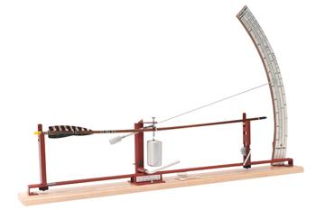
Most commercial and amateur spine testers consist of two supports, either 26 inches or 28 inches apart, a weight of either 2 lb or 1.94 lb to hang on the middle of an arrow, and a method for measuring the deflection – usually either a dial gauge or an arc pointer.
These designs of tester are satisfactory, and are the style of tester mandated in the ATA Technical Guidelines.
The introduction of electronics into a tester allows other testing approaches and facilitates the introduction of other features into the instrument.
Step 11: The Electronic Spine Tester
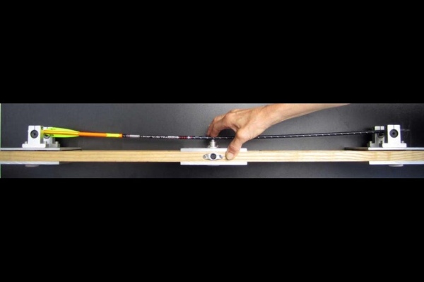
An electronic tester uses a different approach to mechanical testers. Supports at 28 inch spacings are still used, but instead of hanging a weight from the arrow and measuring the deflection, the electronic tester uses the idea of measuring the load required to induce a standard deflection.
It is easy to control the amount of arrow deflection by providing a stop against which to press the arrow.
For example an arrow of spine 500 will by definition deflect ½ inch with a 1.94lb weight hanging from it. Conversely, if a 500 arrow is manually deflected ½ inch it will need a force of 1.98lb. A total force of 1.94lb (or 880g) will therefore be split between the arrow supports, approximately 440g at each.
The mechanism of the tester is to press on the centre of the arrow, deflect it ½ inch, read the forces over and above the weight of the arrow on the supports and arithmetically convert it to a spine number using software in the Arduino.
The model of the 500 arrow is the one used by the software as a standard; it is the simple case – 880g force at the supports = a 500 arrow by definition. Other spines of arrows are a ratio to this arrow. For example 440g force would be a 1000 arrow; 1760g force would be a 250 arrow.
Once electronics are in use other features are easily introduced into the tool such as:
- Display of the arrow spine in any spine methodology.
- Conversion factors between different spine methodologies are either well known, or can easily be derived, and can applied in software.
- Averaging of arrow spines. Arrow spines are often not uniform around the circumference of an arrow; it can be useful to know the average and maximum spine of an arrow and the maximum direction. This is an easy feature to implement in software.
- Weighing of arrows. It is useful to know the weight of arrows to make sure that all are of similar weight. The mechanics of the tool are weighing the arrow as part of the spine calculation so this is an easy feature to provide.
- Calculation of the centre of gravity of the arrow. Arrow centre of gravity affects arrow stability . Centre of gravity calculation is a simple extension of the arrow weighing facility.
- Although not implemented in this version, an electronic spine tester can in theory be interfaced to other electronic devices. The software could easily be extended to interface to a PC using the Arduino’s onboard USB interface, for example.
In addition to these features, there are other advantages to an electronic arrow spine tester over purely mechanical ones:
- It is more compact and more portable. A spine tester with a pointer and dial is incredibly unwieldy and difficult to transport without disassembly. A spine tester with a dial gauge is better but still not compact.
- There is also scope (although not implemented in this version) to shorten the support spacing of 28 inches and make the tester length smaller, scaling the readings up in software. A shorter tester is less unwieldy and can be used on shorter arrows.
- It is potentially cheaper to make. Although dial gauges are becoming much cheaper to buy, to get a full range of spine readings (eg 250 – 1200) a dial gauge of at least an inch and a half of stroke (measurement range) is needed; for ease of use ideally more. Dial gauges with this range of measurement are less common and more expensive.
- It is more robust. Arc pointers are easily damaged and dial gauges become inaccurate if mishandled.
Step 12: Constructing the Arrow Spine Tester
This Instructable gives detailed instructions for building the Electronic Spine Tester in the photographs This version could be simplified in your build. Some dimensions of the spine tester are critical; others have simply been chosen for convenience and can be altered at will.
A Note On Units: Archery generally uses Imperial Units (i.e. inches, pounds, grains). This is in part due to tradition, and in part due to the domination of the American manufacturers who all work in Imperial. As a result, some dimensions are constrained to be in Imperial (or at least it only makes sense to measure them in Imperial), whereas others are metric (e.g. mounts for load cells are invariably metric threads).
Other dimensions in the plans are metric but only for convenience; for example base plates are specified to be 125mm square but could easily be 5 inches (or 4 or 6 if that is what is available). Similarly fasteners are metric threads but these could easily be swapped for imperial fasteners if that is what is available to you.
Internally the software works in metric units for convenience of the calculations, but the interface is in Imperial units to correspond to the measurements with which archers are familiar.
Step 13: Electronics
The software runs on an Arduino microcontroller. An Arduino Nano is is specified in the plans but in principle any Arduino will work (although probably circuit and software changes will be needed).
The build assumes familiarity with Arduinos and the Arduino software build environment; if this is not true then the builder should familiarise themselves with Arduinos using the excellent Arduino tutorials available:
where the exercises will provide excellent experience.
If the builder does not have experience with interfacing load cells to an Arduino using HX711 boards, then a build such as:
https://www.instructables.com/Arduino-Scale-With-5…
which makes a simple scale will be invaluable, and the parts can later be reused in the spine tester build.
Experience assembling electronics projects is also assumed. The electronics are quite simple and are shown assembled on a Vero board; this is perfectly adequate but the builder can upgrade to a printed circuit board if desired.
Step 14: Building the Mechanics
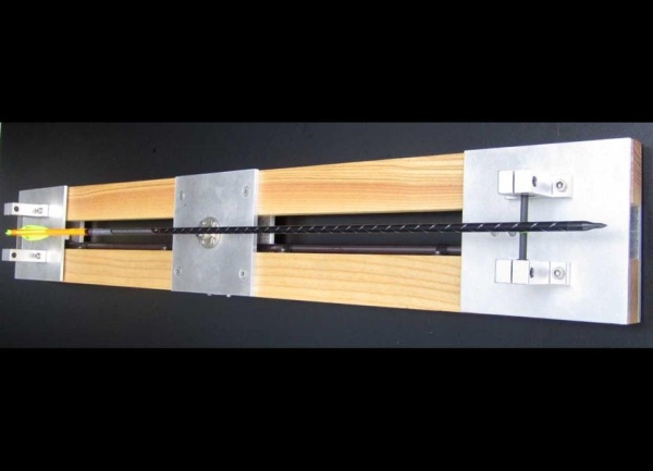
The tool consists of two identical end plinths providing arrow supports and a central plinth with an arrow stop. These plinths are fixed to two wooden rails.
The ATA guidelines specify that the supports must provide free axial travel of the arrow. The support rods are supported by ball bearings to allow this free travel.
Ball bearings are good for maximum accuracy but the longitudinal displacement of the arrow is minimal in use and simpler bearings, such as teflon, or even a small amount axial of compliance in the supports would probably be sufficient.
Whatever design is used, however, it is vital that the plinths are as stiff as possible vertically; every thousandth of an inch of flex in the plinth structures leads directly to exactly that amount of error in reading.
It is also important that when installed on the wooden rails, the spacings of the arrow support rollers are exactly 28 inches apart. For this reason it is suggested that the plinths bolt to the wood through slightly oversized or slotted holes to allow for minor adjustments.
Under the arrow supports are load cells used to measure downward force, and an HX711 interface board to interface to the Arduino.
The middle plinth is simply a support for the stop onto which the arrow is pressed. The design is again not critical apart from being as stiff as possible vertically; again every thousandth of an inch of flex in the plinth leads directly to exactly that amount of error in a spine reading.
It is recommended that the arrow stop is threaded to simplify precise adjustment. The central plinth must be exactly half an inch below the bottom of the arrow and screw adjustment makes small adjustments much easier.
The arrow stop is exactly half way between the arrow supports. Again it is suggested that the plinth bolt to the wood through slightly oversized or slotted holes to allow for minor adjustments.
The wooden rails could easily be changed for some other material, for example aluminium extrusion(s) would work well but would necessitate re-engineering the plinths. The only caveat is that the rails again must be stiff to negate flexing.
Assembly
Assemble the end and middle plinths according to the exploded assembly drawings.
When mounting the load cells take care not to damage the wiring or resistance grids under the protective plastic. Wrap the HX711s in Kapton tape or insulating tape and mount them beside the cells. Extend the wiring from the HX711s to a convenient location using shielded cable and then on to the control box containing the electronics. You may wish to use a suitable plug and socket to ease storage.
Step 15: End Plinth Exploded Drawing
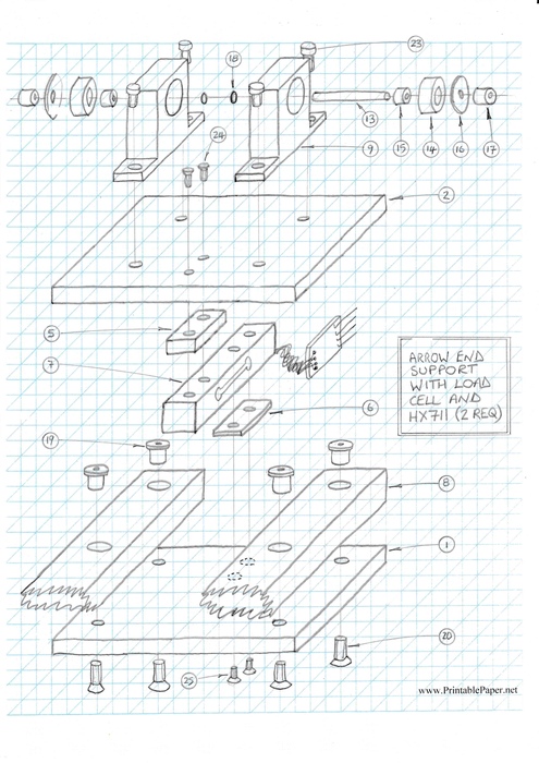
An exploded drawing showing the assembly of an end plinth.
Step 16: Central Plinth Exploded Drawing
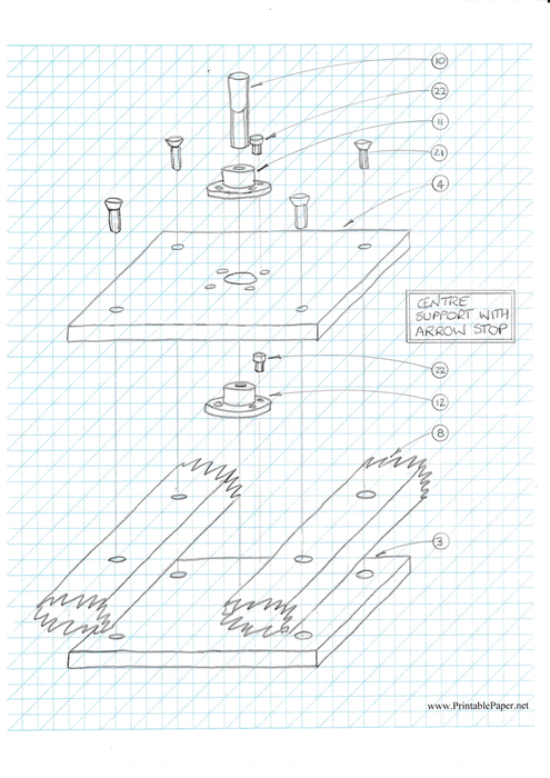
An exploded drawing showing the assembly of the central plinth.
Step 17: Mechanical Parts
A mechanical parts list in Open Document Text format is attached.
Notes on the Parts:
125mm x 125mm aluminium plates, drilled and tapped as per drawings
125mm x 125mm is chosen as a size that will comfortably contain the load cells and HX711 interface board. The width could be reduced if narrower rails were to be used but the length is constrained by the size of the load cells. The position and size of some of the holes is determined by sizes and mounting hole positions of other parts, e.g. the load cells and shaft end supports.
Check your parts before drilling. The thickness of the plates is chosen for stiffness and ease of threading. Thinner plates could be used at your own discretion.
The thickness variation (6mm / 4mm) exists only to give the plates a somewhat consistent level top surface across the three plinths; it is aesthetic only and not vital. load cell spacers sized and drilled as per drawings.
load cell spacers sized and drilled as per drawings
Load cells must have spacers to allow them to flex while working. It is important to note that the top plate of the end plinths has a 2mm gap above the wood rails. This gap allows the load cells to flex. The only connection between the top plate and the bottom is through the load cell. The thickness of the spacers are chosen to provide this gap. If the load cell is of an unusual size or a different rail thickness is chosen then the spacer thickness will need to be varied to maintain that 2mm gap.
2kg load cells and HX711 interface boards
2kg load cells provide a good capacity. 1Kg units could theoretically be ok but would be very marginal. A 250 arrow would impart a 880g load on each cell which would only leave 120g for the weight of the plinth. This design exceeds that weight. This is unfortunate as a 1kg load cell would theoretically have twice the precision. A lighter design of plinth could allow a 1kg load cell to be used. On the other hand a 2kg load cell is more robust.
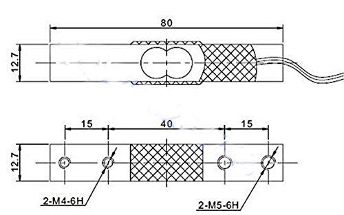
The design uses load cells with the following dimensions shown in the attached picture.
If load cells of other dimensions are used then the design will need adjusted as the load cells and HX711 boards mount between the rails.
hardwood rails 44mm x 19mm x 33 inches long
Different dimensions or materials could be used but stiffness must be maintained, as must space for the load cells.
SK16 shaft end supports
SK16 shaft supports are generally available on auction sites as they are used by prototypers and hobbyists making things like linear actuators, CNC machines, and 3D printers. They usually support round bars; here they are used to house small 16mm bearings.
M10 x 1.5 x 50mm partial thread bolt with head removed
rigid shaft couplings
These parts form the arrow stop. The stop itself is an M10 bolt with the head cut off. This is mounted vertically through the upper and lower plates of the central plinth.
Rigid shaft couplings are basically locking collars or collets with grub screws and a flange. They are normally used to connect two rotating shafts together rigidly, or a shaft to an electric motor. Here they are used to connect the arrow stop (bolt) to the plates in an adjustable fashion.
The bottom coupling has an 8mm hole tapped to M10. The upper has a 10mm hole. This allows the bolt to screw into the bottom coupling and be clamped in position with the grub screws in the top coupling.
A simpler method would be to simply tap the hole bottom plate to M10 but this would not provide as much adjustment.
A partially threaded bold is chosen to allow the grub screws to clamp to a flat surface rather than a threaded one.
Threaded M10 rod could be used instead.
5mm diameter carbon fibre rods 76mm long
ball bearing 8mm x 16mm x 5mm
spacers 5mm bore, 8mm OD length 5mm
Teflon washers 5mm bore, 16mm OD, 1mm thick 5mm bore
shaft locking collar
The carbon fibre rods, bearings and associated parts form the roller supports on which the arrow sits. An arrow was used as the carbon fibre rod; any rigid rod would do however.
The ATA specifies a support of ¼ inch / 6mm or less. Hence 5mm was chosen.
The spacer takes up the gap between the 8mm interior hole of the bearing and the 5mm rod. A simpler build would use an 8mm rod; this would violate the ATA spec however. Smaller bearings would also be a possibility. But, the spacer and the locking collars must be sized to the rod diameter.
The Teflon washers sit between the bearing and locking collar; the size is actually not critical as long as they do not rattle around.
‘O’ rings 5mm ID
The ‘O’ rings are placed on the rods near the middle in pairs to keep the arrow central on the support rod. The rod (and by implication the SK16s) needs to be wide enough to give clearance for fletches but the arrow needs to be central for good measurements.
8 off M5 T nuts without barbs
T nuts are used to make bolting the end support bottom plates to the bottom rails easier. Making them loose in the wooden rails can give one or two mm of adjustment for fine tuning. Wood screws could be used but this would not allow the same adjustment.
Bolts
Apart from one or two special instances where components require particular bolt and thread sizes, most bolt diameters are chosen for convenience, and lengths chosen so as to not protrude from component faces.
If the sizes are deviated from then the mounting plate designs will need to be altered.
Note that other design changes may need bolts of different lengths.
If thread cutting equipment is not available then nuts and bolts can be used but thought will have to be given to clearances and methods of assembly.
Source: Electronic Arrow Spine Tester
