Summary of Driving two Nixie tubes with an Arduino via a shift register and two SN74141s
Nixie tubes are driven here using an Arduino, an SN74HC595 shift register, and two SN74141 BCD-to-decimal decoder/driver chips to minimize Arduino pins and simplify high-voltage cathode switching. The shift register provides serial-to-parallel outputs that feed the 74141s, which connect the selected Nixie cathode to ground while a separate high-voltage anode lights the chosen digit. The design supports daisy-chaining additional tubes and requires a common ground and appropriate current-limiting resistors and a 150–180 V HV supply. Safety warnings about high voltage are emphasized.
Parts used in the Nixie tube shift-register project:
- Arduino development board (example: Freeduio)
- Two IN-12b Nixie tubes with sockets
- Two SN74141 BCD-to-decimal decoder/driver chips (or K155ID1)
- One SN74HC595N shift register
- High-voltage power supply for Nixie tubes (150–180 V)
- 12 V power supply (wall wart) for the HV supply
- Two current-limiting resistors (example: 1 W 4.7 kΩ)
- Breadboard
- Jumper wires
- Solder and leads for Nixie tube sockets
Nixie tubes are really cool looking and are becoming quite popular for their ‘retro’ look. Although there are a number of tutorials out there on using nixie tubes and some nice pre-packaged units (see these nice ones from ogi lumenand ArduiNIX) I hadn’t seen a simple tutorial on running them using a shift register like the SN74HC595. This would use the minimum number of Arduino pins as it can run as a serial device. Another nice addition is the use of the SN74141 BCD to decimal decoder/driver chip. This chip allows direct control of the Nixie tubes from the shift registers without the use of individual transistors for each numeral. An added benefit to using shift registers is that additional pairs of Nixie tubes can be added without using any more Arduino output pins. They just get daisy chained to the first set.
 WARNING: Nixie tubes require a high voltage power supply, typically 150-180 volts. This is enough voltage to hurt you. Please make sure you know what you are doing.
Note: please let me know of any typos/errors/comments so I can continue to improve this Instructable.
I’d also appreciate it if you’d vote for me in the contest. Thanks.
Step 1: Theory
This byte is then passed serially to the shift register.
The shift register then uses the byte to set each of eight pins either high or low (aka serial to parallel conversion). (A useful tutorial using shift registers with Arduinos can be found here)
These eight pins are connected to the input pins (four each) on the two 74141 chips.
The 74141 chips read the four bits as a code that defines which of the numbers to light on the Nixie tube. See the datasheet for the codes)
A Nixie tube works by having a high voltage (typically 150 – 180 volts) attached to the anode. Each of the filaments is connected to the anode and each has a separate cathode. When a number’s cathode is connected to ground, current flows through the digit and it lights up).
The 74141 chip is designed to interpret the four bit code to connect one of its ten pins to ground. The 10 cathodes of the Nixie tube are connected to these pins. When one of these pins gets connected to ground, that number lights up. The 74141 is specially designed to handle the Nixie’s high voltages.The same thing could be done with a series of transistors, but the 74141 chip just simplifies things.
Step 2: Get the stuf
You will need the following:
An Arduino development board of some type. I’m using a Freeduio from NKC Electronics
Two IN-12b nixie tubes with sockets (I found some on eBay)
Two SN74141 BCD chips (or the Soviet equivalent; K155ID1, also from eBay, see above)
One SN74HC595N shift register (very common, e.g. Adafruit)
A high voltage power supply for the Nixie tubes (I used this one, see the picture)
A 12 volt power supply for the high voltage power, I used a 12 volt wall wart.
Two current limiting resistors, one for each Nixie tube. I used a 1 watt 4.7 kohm.
A breadboard and some jumpers
Step 3: Setting up
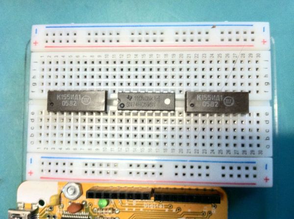
You’ll want to place the shift register in the middle of the breadboard and the two 74141 chips on either side of it. I’ve added a mounting spot to my breadboard to hold the Arduino. It just needs to be close by.
Assemble the high voltage (HV) power supply per its directions. The ground for the HV supply needs to be common to the Arduino and the rest of the circuit. Keep the HV line away from the normal five volt power line or bad things will happen. Please read all of the warning associated with your HV power supply and remember that this is enough voltage to hurt you.
Step 4: Wiring the Nixie tubes
On the bottom of the Nixie tube socket each of the leads is numbered. Solder 4-6″ leads on to each of these connections (you can ignore pin 12 as it does not get used). Note that the socket has a notch in it near pin one.
Identify pin one on the Nixie tube. Looking at the top of the tube, the number 3 will be on top. Pin 1 is at about 5 o’clock when holding the Nixie tube with the digit 3 upright. On my tubes this pin was painted white to differentiate it.
Place the Nixie tube in the socket so pin 1 is near the notch in the socket.
Connect the 11 leads in order to 11 rows of the breadboard near one of the 74141 chips.
Repeat for the second Nixie tube.
For more detail: Driving two Nixie tubes with an Arduino via a shift register and two SN74141s
- How does the shift register reduce Arduino pin usage?
The Arduino sends a byte serially to the SN74HC595 which converts it to eight parallel outputs, minimizing required Arduino pins. - Can additional Nixie tubes be added without using more Arduino pins?
Yes, additional pairs of Nixie tubes can be daisy chained to the shift register without using more Arduino output pins. - What role do the SN74141 chips play?
The SN74141 chips read four input bits and connect one of ten outputs to ground, directly driving the Nixie tube cathodes for the selected numeral. - Does the project require a high-voltage supply?
Yes, Nixie tubes require a high-voltage power supply typically 150 to 180 volts. - How are the Nixie tube digits illuminated?
The tube anode is tied to the HV supply and when a cathode is connected to ground by the 74141, current flows through that digit and it lights. - What safety precautions are mentioned?
Warning that the 150–180 V HV can hurt you and to ensure you know what you are doing and follow HV supply warnings. - Do the 74141 chips handle the high voltages directly?
Yes, the 74141 is designed to handle the Nixie tubes high voltages and simplifies wiring compared to using transistors. - How should grounds be arranged?
The ground for the HV supply needs to be common with the Arduino and the rest of the circuit. - What resistors are needed?
Two current-limiting resistors, one per Nixie tube, are used; the example given is 1 watt 4.7 kΩ. - How are the Nixie tube socket leads prepared?
Solder 4–6 inch leads to each socket pin (ignore pin 12), identify pin 1, and connect the socket leads to breadboard rows near the corresponding 74141.