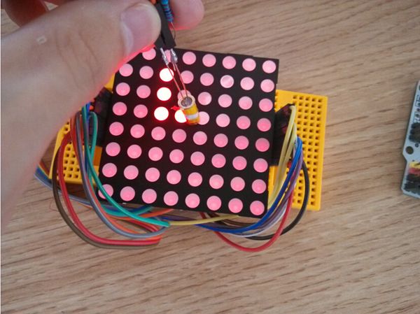
In the current market where capacitive touch screens, resistive touch screens, TFT displays are flooding, DIY enthusiasts have been rarely used dot matrix screens. Here we use 5mm 8 * 8 dot matrix screen and phototransistor to achieve a pen write function. Sounds fun? But how to specifically make it? Can we achieve a larger area pen write? Just read on to know.
I. Target
To realize pen write on dot matrix.
II. Hardware
LED matrix, UNO, flowerpad, 74ls138, PNP transistor, LM358, photosensitive triode, resistors (22K, 1K), pins
III. Circuit
The project is mainly composed of three parts: row scan circuit, column scan circuit, the pen’s circuit. The principle block is as shown below. It has a photosensitive sensor in the pen, we use this pen to get the states of LED.
1. Row scan
Make decoder’s Y0, Y1…effective in turn, but 74ls138 output low level on corresponding pin if have a effective input, because our dot matrix is common anode, we need an inverter, we use PNP transistor to constitute a inverter. Every eight times column scanning on a row scan.
2. Column scan
Make decoder’s Y0, Y1…effective in turn, and input PWM on OE1, if OE1 is high level, Y0~Y7 are high level,if OE1 is low level, ABC pin decide decoder’s output. When enable some line, we make decoder’s Y0, Y1…effective in turn, and we can control every LED’s brightness by OE1.
3. Pen
Set the reference voltage at the inverting input of comparator at a certain value, and in-phase input voltage will be less than this value when the pen receives light, vice versa. The current through R3 is very small if light is insufficient, so in-phase input voltage will be closer to the power supply voltage, and comparator outputs high level. The current through R3 will increase if light intensity increases, and the voltage of R3 will increase, so in-phase input voltage will decrease, then comparator outputs low level. MCU can catch this change and then does the corresponding processing.
IV. Program Analysis
To detect state of the points on the dot matrix we must light LED, and make it in the dim state, when the pen gets close to some point, we set the point highlight. But how do we know the coordinates of this point? The principle is: let LED light up one by one,the first of the first line, then the second of the first line…, until the last of the first line. Turn again the first of the second line, light up LED in turn in a loop. Every LED has state value: 0 stands for the dim state, 1 stands for highlight state. When the pen gets close to some point but it’s not the point’s turn to light up, because the pen did not detect light,it maintains a high level at the output of the comparator. When it’s turn to light up this point, comparator outputs a low level, MCU executes interrupt program when it detect a level change, and gets value of current row and column, then set state that find the point by value of row and column of 1, and set it to highlight state when it’s lighted up next time. We see the whole dot matrix light up when increasing scanning speed, rather than one by one.
For more detail: Dot Matrix Pen Write Screen