
Summary of A Digitally Controlled Dual Tracking Power Supply
This article details a digitally controlled dual tracking ±30V linear power supply project utilizing a 540VA Deltron W127G transformer. The design supports up to 10 Amps per channel with constant voltage and current modes. Key features include four parallel TIP35C transistors in a Sziklai pair to handle high power dissipation, operational amplifiers for control loops, and buffering stages between the DAC and OpAmps to ensure stability and protect the microcontroller from potential failures.
Parts used in the Digitally Controlled Dual Tracking Power Supply:
- Deltron W127G open-frame power supply transformer (28V+28V, center tapped)
- Four TIP35C NPN transistors
- Digital-to-analog converter (DAC)
- Microcontroller Unit (MCU)
- Operational Amplifier IC1A
- Operational Amplifier IC1B
- Voltage follower buffer
- Protection diodes
- Resistor divider R10
- Resistor divider R11
In my previous post, I showed my design of a dual tracking ±30V linear power supply.
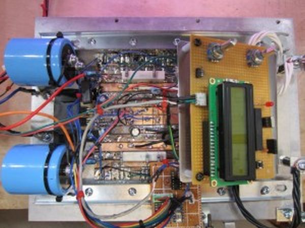
My goal was to use the transformer (28V+28V, center tapped) from an old Deltron W127G open-frame power supply and build a lab supply that can be digitally adjusted in both constant voltage and constant current modes. I also wanted each of the channels to be able to deliver up to 10 Amps of current so that I could fully utilize the 540VA transfomer from the W127G.
The following is the finalized schematic for the positive power supply portion (pretty much identical to the schematic I used in my simulations earlier). Here, I used four TIP35C‘s in parallel as the NPN transistor in the Sziklai pair. Because the input voltage is fixed at roughly 30V under maximum load, in a dead short scenario the power dissipated in the pass transistors is at least 300W and thus four transistors are needed to be able to share this worst case load. If you are building a power supply that is rated for just a couple of Amps, you can use just a single power transistor. I also added a buffer between the DAC and the voltage control loop OpAmp (IC1A) to improve stability. Because the digital/analog converter is not isolated, using a buffer between the DAC and the control point can greatly reduce the risk of damaging the DAC or the MCU should one of the OpAmps fail during operation. Similarly, a voltage follower was also added to buffer the current setting output from IC1B. The protection diodes were included to protect the inputs of the OpAmps during large voltage swings in transient events (such as power on).
The temperature stability of the regulated output voltage is largely dependent on the temperature coefficients of the resistor divider R10 and R11. As I explained previously, the output voltage is determined by:
For more detail: A Digitally Controlled Dual Tracking Power Supply
- What is the maximum current each channel can deliver?
Each channel can deliver up to 10 Amps of current. - How many TIP35C transistors are used in parallel?
Four TIP35C transistors are used in parallel as the NPN transistor in the Sziklai pair. - Why are four transistors needed for this specific load?
Four transistors are required because the power dissipated in the pass transistors is at least 300W during a dead short scenario. - Can a single transistor be used if the rating is lower?
Yes, if building a power supply rated for just a couple of Amps, you can use just a single power transistor. - What is the purpose of the buffer between the DAC and the OpAmp?
The buffer improves stability and reduces the risk of damaging the DAC or MCU should an OpAmp fail. - Why were protection diodes included in the circuit?
Protection diodes protect the inputs of the OpAmps during large voltage swings in transient events like power on. - Which components determine the temperature stability of the output voltage?
The temperature stability is largely dependent on the temperature coefficients of resistor divider R10 and R11. - Is the digital/analog converter isolated in this design?
No, the digital/analog converter is not isolated.
