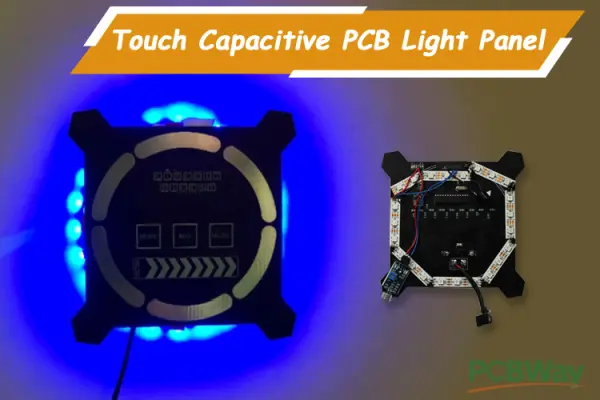
In this guide, we will illustrate the process of crafting a touch capacitive PCB with an ATMega328P IC, designed to oversee Neo-Pixel LED strips. Our PCB boasts versatile capabilities, encompassing music-reactive, random animation, and RGB control modes. Building on our prior exploration of touch capacitive technology in the touch capacitive piano tutorial, this project focuses on designing a touch capacitive-based light panel with three distinct modes for NeoPixel strip control.
These modes encompass the ‘Ring Mode,’ which allows color adjustments via sliders on the board, the ‘RGB Mode’ permitting color and intensity modifications within the RGB spectrum, and finally, the ‘Music Mode,’ where LED colors and intensities synchronize with the playing music. This sophisticated project became a reality thanks to PCB boards manufactured by PCBWay, and we’ll also elucidate the process of designing and ordering these boards from PCBWay.
Materials needed for constructing the front panel PCB.
To assemble a PCB piano with an Arduino Nano, you’ll need the subsequent components.
- ATMega328P IC (DIP Package)
- SMD Resistors (1Mega Ohm, 0805) X 9
- SMD Resistors (1K, 0805)x1
- Piezoelectric Buzzer
- SMD 78M05 IC
- SMD Electrolytic Capacitor (10uF,16V,4x45mm) x 2
- SMD Capacitor ( 22pF 0805) x 11
- Crystal Oscillator (16 MHz)
Schematic illustration of the PCB light panel circuit
In the given circuit diagram, nine 1 Mega Ohm resistors are linked to Pin PB1 of the ATMega328P IC, serving as a common connection point. Additionally, digital pins PD2 to PD7 and PB0 are connected to the corresponding terminals of each resistor. In the diagram below, the remaining digital pins are interfaced with a 1×5 pin header and labeled as “REMAINING DIGITAL PINS.”
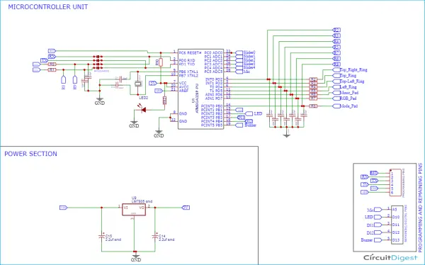
We’ve established a connection involving eight 22uF capacitors, with each capacitor connected to a corresponding resistor. Furthermore, the negative terminal of each capacitor is linked to the ground pin of the Atmega328p IC. In addition, there’s a power section responsible for supplying a stable 5V to both the ATMega328P IC and the Neo Pixel
Please take note: If deemed necessary, capacitors can be incorporated. It is highly advisable to employ small capacitors within the range of 20pF to 400pF to ensure stable data detection. It’s important to ground these capacitors, as doing so mitigates the parallel resistance to the body. In my personal case, I opted not to utilize capacitors because the system functions adequately without them. However, I have included references to capacitors in the schematic above to facilitate their inclusion during practical implementation. It’s worth emphasizing that the values of these capacitors must fall within the 20pF to 400pF range, as specified in the documentation of the “Capacitive Sensor” library
What is the functioning principle of the Capacitive Sensor Library?
This is where Arduino libraries become invaluable, and credit goes to the creators of the “Capacitive Sensor” library, Paul Badger and Paul Stoffregen. When we touch the conductive plate, this library allows us to detect a change in capacitance. In this library, one of the digital pins functions as a send pin (set as OUTPUT), while the other serves as a receive pin (set as INPUT). The crucial aspect of detecting capacitance changes lies in the time interval between when the send pin goes high and when the receive pin also goes high.
Upon setting the send pin to a high state (or 5 volts), the resistor-capacitor pair introduces a delay between the moment the send pin becomes high and when the receive pin registers a high value from the send pin. The Capacitive Sensor library furnishes a function that elevates the send pin to HIGH, subsequently monitoring and counting the time until the receive pin reaches a HIGH state. This function returns a time value, which is instrumental for discerning changes in capacitance.
When the time value increases or decreases, it signifies alterations in capacitance. A greater capacitance will cause the receive pin to take more time to reach the high state, whereas lesser capacitance will result in a shorter duration. Consequently, we can establish a baseline for the normal state and then monitor for changes each time the send pin toggles.
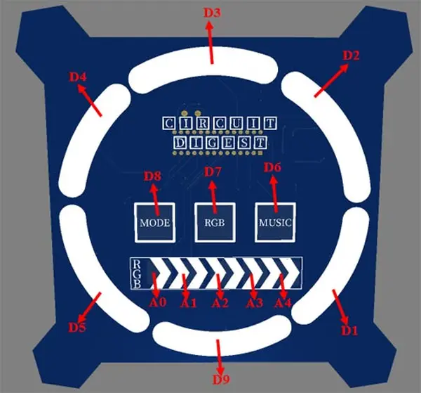
Creating a printed circuit board (PCB) for the light panel PCB
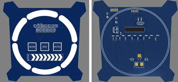
With the schematic in hand, we can now move forward to design the layout of the PCB for the Touch Capacitive Based PCB Light Panel. You have the flexibility to employ any PCB software you prefer for this task. In our case, we are utilizing the EasyEDA platform to craft both the schematic and the PCB for our project. Provided below are 3D model perspectives showcasing the top and bottom layers of the PCB Light Panel.
Placing an order for PCBs through PCBWay
Now, once you’ve completed the design to your satisfaction, you can proceed to place an order for the PCB:
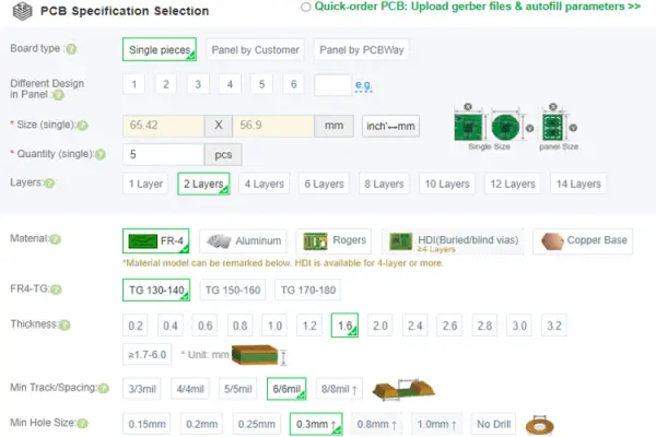
Step 1: Visit https://www.pcbway.com/ and, if you’re a first-time user, create an account. Next, navigate to the “PCB Prototype” section and input your PCB’s dimensions, the desired number of layers, and the quantity of PCBs you need.

Step 2: Continue by selecting the “Quote Now” button. This will direct you to a page where you can specify additional parameters such as the board type, number of layers, PCB material, thickness, and more. Many of these options come with default selections, but if you have specific preferences, you can make your choices on this page.
Step 3: The last step involves uploading the Gerber file and completing the payment. PCBWAY conducts a verification process to ensure the validity of your Gerber file before proceeding with payment. This ensures that your PCB is fabrication-ready and will be delivered to you as promised, without any issues.

Putting together the PCB for the Touch Capacitive Light Panel
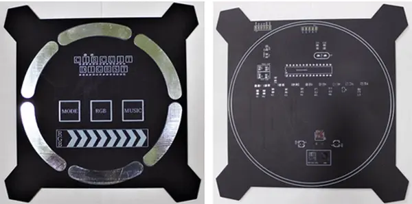
Following the order placement, the PCB arrived at my location within a few days, delivered by a courier service. It was meticulously labeled and thoughtfully packaged in a well-organized box. The PCB’s quality met my expectations, consistent with my previous experiences. You can observe both the top and bottom layers of the board below for reference.
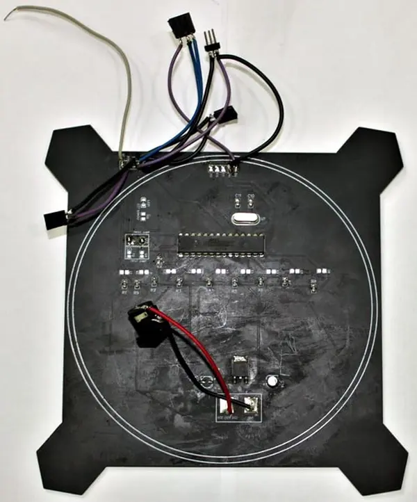
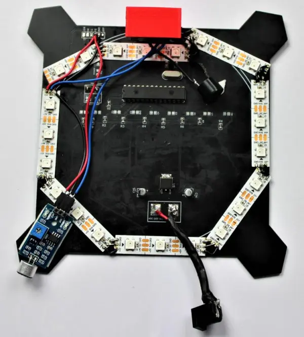
After confirming the accuracy of the tracks and footprints, I proceeded with the PCB assembly. The finished soldered board is depicted below:
Programming the PCB Light Panel
The complete code for the PCB Light Panel based on touch capacitive technology is available for download from the project’s GitHub repository. The “CapacitiveSensor” library is exceptionally user-friendly, and it comes with comprehensive documentation on how to utilize it effectively. Before delving into the program, let’s first install the “CapacitiveSensor” library in the Arduino IDE.
To do this, download the library’s zip file and navigate to the “Sketch -> Include Library” section in the Arduino IDE toolbar. Add the zip file by selecting the “Add .Zip Library…” option, as illustrated in the image below. Afterward, restart the Arduino IDE. You can similarly install the ADCTouch.h library using a similar process.
Once you have successfully installed the necessary library files, commence the code by incorporating all the required libraries. The Adafruit_NeoPixel.h library is employed for managing single-wire-connected LED pixels and strips. In our setup, we use it to control the Neo-Pixel LED strip. Additionally, the CapacitiveSensor library is utilized to detect touch input on the PCB pads
#include <Adafruit_NeoPixel.h>
#include <CapacitiveSensor.h>
#include <ADCTouch.h>
Following that, in the subsequent lines, we have instantiated nine objects using the CapacitiveSensor() function. These instances specify the pins to which the touchpads are linked. The function’s syntax takes the form of CapacitiveSensor(byte sendPin, byte receivePin), wherein one of the digital pins functions as the send pin (configured as OUTPUT), while the other serves as the receive pin (configured as INPUT) within this library.
CapacitiveSensor   Mode_Pad = CapacitiveSensor(9,8);
CapacitiveSensor   RGB_Pad = CapacitiveSensor(9,7);
CapacitiveSensor   Music_Pad = CapacitiveSensor(9,6);
CapacitiveSensor   Ring_L_Pad = CapacitiveSensor(9,5);
CapacitiveSensor   Ring_LT_Pad = CapacitiveSensor(9,4);
CapacitiveSensor   Ring_T_Pad = CapacitiveSensor(9,3);
CapacitiveSensor   Ring_TR_Pad = CapacitiveSensor(9,2);
Subsequently, declare the Neo Pixel strip object, where the first argument represents the quantity of pixels within the Neo Pixel strip, and the second argument designates the pin to which the LED strip is attached.
Adafruit_NeoPixel strip = Adafruit_NeoPixel(N_PIXELS, PIN, NEO_GRB + NEO_KHZ800);
Following that, we’ve established several functions for detecting touch input on the pads and rings. The initial three functions, specifically ModeMode(), RGBMode(), and MusicMode(), serve to identify touch input on the pads employed to switch between distinct PCB modes.
In the initial function, we examine the values of the first pad, labeled ‘MODE,’ and return 1 if the detected values surpass 500; otherwise, it returns zero. Likewise, two additional functions are defined for the RGB pad and MUSIC pad, each tailored to their respective functionalities.
boolean ModeMode(){
    long Mode_Pad_Value =  Mode_Pad.capacitiveSensor(30;
    if (Mode_Pad_Value>500)
    return 1;
    else
    return 0;
}
boolean RGBMode(){
    long RGB_Pad_Value =  RGB_Pad.capacitiveSensor(30);
    if (RGB_Pad_Value>500)
    return 1;
    else
    return 0;
}
boolean MusicMode(){
    long Music_Pad_Value =  Music_Pad.capacitiveSensor(30);
    if (Music_Pad_Value>500)
    return 1;
    else
    return 0;
}
The Check_Ring_Pos() function serves a dual purpose: it identifies touch input on the rings and retains information about the ring’s position. These ring positions play a crucial role in discerning whether the rings are rotated clockwise or counterclockwise. Similarly, we’ve introduced another function for monitoring slider positions and gauging the swipe direction based on the pad positions along the slider.
char Check_Ring_Pos()
{
    char ring_pos = 0;
    char result = 0;
    long Ring_L_Pad_Value =  Ring_L_Pad.capacitiveSensor(30);
    long Ring_LT_Pad_Value =  Ring_LT_Pad.capacitiveSensor(30);
    long Ring_T_Pad_Value =  Ring_T_Pad.capacitiveSensor(30);
    long Ring_TR_Pad_Value =  Ring_TR_Pad.capacitiveSensor(30);
    if (Ring_L_Pad_Value>500)
    ring_pos = 1;
    if (Ring_LT_Pad_Value>500)
    ring_pos = 2;
    if (Ring_T_Pad_Value>500)
    ring_pos = 3;
    if (Ring_TR_Pad_Value>500)
    ring_pos = 4;
  char current_ring_pos = ring_pos;
  Serial.println(current_ring_pos - pvs_ring_pos);
  if ((current_ring_pos - pvs_ring_pos) == 1)
  result = 1;
  if ((current_ring_pos - pvs_ring_pos) == -1)
  result =2;
  if (current_ring_pos != pvs_ring_pos);
  pvs_ring_pos = current_ring_pos;
  return result;
}
With our ability to determine whether a specific pad was touched and in which direction, we can now leverage these readings to transition between the three modes. In the RGB mode, the slider pads allow us to adjust the brightness of the lights. Swiping from left to right increases the brightness, while swiping from right to left decreases it. Additionally, we can employ the Ring pads, rotating them clockwise or counterclockwise, to alter the colors.
In the Mode mode, the Ring pads come into play, enabling us to rotate the lights in both clockwise and counterclockwise directions.
void RGB_Mode(){
  Serial.print("We have entered RGB Mode");
  beep();
  uint16_t i, j, k;
  Brightness = 255;
  while(1){
  char Sider_Status = Check_Slider_Pos();
  char Ring_Status = Check_Ring_Pos();
  if (Sider_Status ==1){ //return 0 for no movement and 2 for right to left
  Serial.println ("Moved Left to Right");
  beep();
  Brightness = Brightness+50;
  Serial.print(Brightness);
  }
……………………………………..
When the Music Mode pad is touched, the Arduino initiates the process of monitoring the microphone’s output. It subsequently adjusts the intensity and color of the lights randomly in response to the music.
void Music_Mode(){
  Serial.print("We have entered MUSIC Mode");
  beep();
  while(1){
  if (digitalRead(A5)==LOW)
  {
    Serial.print("TAP");
      for(int i=0; i< 48; i++)
  {
     strip.setBrightness(random (100,255));
     strip.setPixelColor(i, strip.Color(random (0,255), random (0,255), random (0,255)));
     strip.show();
  }
Creating the casing for the Touch Capacitive PCB Light Panel using 3D printing
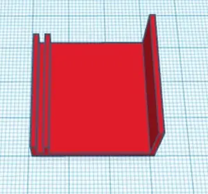
The plan is to mount the PCB light panel on a wall, and to achieve this, I 3D-printed a holder specifically tailored to the PCB. I took measurements of the arrangement using my vernier caliper to create a custom casing. Once the design was complete, it resembled the image below. You can also obtain the STL file for the casing on Thingiverse, allowing you to print your own casing using it.
Evaluating the performance of the Touch Capacitive PCB Light Panel
Now, supply power to the board using a 12V adapter. You can utilize the three touchpads labeled MODE, RGB, and MUSIC to toggle between various modes, and the sliders to modify the light’s brightness and color.
Code
#include <Adafruit_NeoPixel.h>
#include <CapacitiveSensor.h>
#include <ADCTouch.h>
#define PIN 10 //Neo pixel connected to pin 10
#define BUZZER 13 //BUZZER is connected to pin D13
#define N_PIXELS 23 //48 neopixel in led strip
#define MIC A5 // Microphone is connected at pin A5
#define N 10 // Number of samples
#define fadeDelay 25 // fade amount
#define noiseLevel 25 // Amount of noice we want to chop off
int ref1,ref2,ref3, ref4,ref5;       //reference values to remove offset fro using analog pins are capacitive touch
char pvs_slider_pos = 0;
char pvs_ring_pos = 0;
int samples[N]; // storage for a sample
int periodFactor = 0; // For period calculation
int t1 = -1;
int T;
int slope;
byte periodChanged = 0;
int Brightness=0;
int led_position=0;
CapacitiveSensor   Mode_Pad = CapacitiveSensor(9,8);
CapacitiveSensor   RGB_Pad = CapacitiveSensor(9,7);
CapacitiveSensor   Music_Pad = CapacitiveSensor(9,6);
CapacitiveSensor   Ring_L_Pad = CapacitiveSensor(9,5);
CapacitiveSensor   Ring_LT_Pad = CapacitiveSensor(9,4);
CapacitiveSensor   Ring_T_Pad = CapacitiveSensor(9,3);
CapacitiveSensor   Ring_TR_Pad = CapacitiveSensor(9,2);
//create a NeoPixel strip
Adafruit_NeoPixel strip = Adafruit_NeoPixel(N_PIXELS, PIN, NEO_GRB + NEO_KHZ800);
boolean ModeMode(){
    long Mode_Pad_Value =  Mode_Pad.capacitiveSensor(30);
    if (Mode_Pad_Value>500)
    return 1;
    else
    return 0;
}
boolean RGBMode(){
    long RGB_Pad_Value =  RGB_Pad.capacitiveSensor(30);
    if (RGB_Pad_Value>500)
    return 1;
    else
    return 0;
}
boolean MusicMode(){
    long Music_Pad_Value =  Music_Pad.capacitiveSensor(30);
    if (Music_Pad_Value>500)
    return 1;
    else
    return 0;
}
char Check_Ring_Pos()
{
    char ring_pos = 0;
    char result = 0;
    long Ring_L_Pad_Value =  Ring_L_Pad.capacitiveSensor(30);
    long Ring_LT_Pad_Value =  Ring_LT_Pad.capacitiveSensor(30);
    long Ring_T_Pad_Value =  Ring_T_Pad.capacitiveSensor(30);
    long Ring_TR_Pad_Value =  Ring_TR_Pad.capacitiveSensor(30);
    if (Ring_L_Pad_Value>500)
    ring_pos = 1;
    if (Ring_LT_Pad_Value>500)
    ring_pos = 2;
    if (Ring_T_Pad_Value>500)
    ring_pos = 3;
    if (Ring_TR_Pad_Value>500)
    ring_pos = 4;
  char current_ring_pos = ring_pos;
  Serial.println(current_ring_pos - pvs_ring_pos);
  if ((current_ring_pos - pvs_ring_pos) == 1)
  result = 1; //Serial.print("Ring touched clockwise");
  if ((current_ring_pos - pvs_ring_pos) == -1)
  result =2; //Serial.print("Ring touched counter clockwise");
  if (current_ring_pos != pvs_ring_pos);
  pvs_ring_pos = current_ring_pos;
  return result;
}
char Check_Slider_Pos()
{
    char slider_pos = 0;
    char result = 0;
    int sensorValue1 = ADCTouch.read(A0);
    int sensorValue2 = ADCTouch.read(A1);
    int sensorValue3 = ADCTouch.read(A2);
    int sensorValue4 = ADCTouch.read(A3);
    int sensorValue5 = ADCTouch.read(A4);
    sensorValue1 -= ref1;
    sensorValue2 -= ref2;
    sensorValue3 -= ref3;
    sensorValue4 -= ref4;
    sensorValue5 -= ref5;
    if (sensorValue1>50)
    slider_pos = '1';
    if (sensorValue2>50)
    slider_pos = '2';
    if (sensorValue3>50)
    slider_pos = '3';
    if (sensorValue4>50)
    slider_pos = '4';
    if (sensorValue5>50)
    slider_pos = '5';
  char current_slider_pos = slider_pos;
  if ((current_slider_pos - pvs_slider_pos) == 1)
  result = 1; //Serial.print("Slider Left to Right");
  if ((current_slider_pos - pvs_slider_pos) == -1)
  result =2; //Serial.print("Slider Right to Left");
  if (current_slider_pos != pvs_slider_pos);
  pvs_slider_pos = current_slider_pos;
  return result;
}
void RGB_Mode(){
  Serial.print("We have entered RGB Mode");
  beep();
  uint16_t i, j, k;
  Brightness = 255;
  while(1){ //Stay in RGB mode
  char Sider_Status = Check_Slider_Pos();
  char Ring_Status = Check_Ring_Pos();
  if (Sider_Status ==1){ //return 0 for no movement and 2 for right to left
  Serial.println ("Moved Left to Right");
  beep();
  Brightness = Brightness+50;
  Serial.print(Brightness);
  }
  if (Sider_Status==2){ //return 0 for no movement and 2 for right to left
  Serial.println ("Moved Right to Left");
  beep();
  Brightness = Brightness-50;
  Serial.print(Brightness);
   }
  if (Ring_Status==1) {//return 0 for no movement and 2 for counter clockwise
  Serial.println ("Ring in Clockwise");
  beep();
  i = random (0,255);
  j = random (0,255);
  k= random (0,255);
  }
  if (Ring_Status==2) {//return 0 for no movement and 2 for counter clockwise
  Serial.println ("Ring in Counter-Clockwise");
  beep();
  i = random (0,255);
  j = random (0,255);
  k= random (0,255);
  }
  for(int x=0; x<N_PIXELS; x++) {
            strip.setBrightness(Brightness);
            strip.setPixelColor(x, strip.Color(i,j,k));
            strip.show();
          }
  if ( RGBMode() || ModeMode() || MusicMode())
  break;
  }
}
void Mode_Mode(){
  Serial.print("We have entered MODE Mode");
  beep();
  while(1){ //Stay in RGB mode
  char Ring_Status = Check_Ring_Pos();
  if (Ring_Status==1) {//return 0 for no movement and 2 for counter clockwise
  Serial.println ("Ring in Clockwise");
  beep();
  }
    for(int i=0; i< 48; i++) {
     strip.setBrightness(255);
     strip.fill(255,(i+0),(1+i));
     strip.fill(0,0,i);
     strip.show();
     delay(20);
  }
  if (Ring_Status==2){ //return 0 for no movement and 2 for counter clockwise
  Serial.println ("Ring in Anti- Clockwise");
  beep();
  for(int i=48; i>0; i--) {
     strip.setBrightness(255);
     strip.fill(255,(i+0),(1+i));
     strip.fill(0,0,i);
     strip.show();
     delay(20);
  }
  }
  if ( RGBMode() || ModeMode() || MusicMode())
  break;
  }
}
void Music_Mode(){
  Serial.print("We have entered MUSIC Mode");
  beep();
  while(1){ //Stay in RGB mode
  if (digitalRead(A5)==LOW)
  {
    Serial.print("TAP");
      for(int i=0; i< 48; i++)
  {
     strip.setBrightness(random (100,255));
     strip.setPixelColor(i, strip.Color(random (0,255), random (0,255), random (0,255)));
     strip.show();
  }
  delay(100);
  }
  else
  {
  for(int i=0; i< 48; i++)
  {
     strip.setBrightness(0);
     strip.setPixelColor(i, strip.Color(random (0,255), random (0,255), random (0,255)));
     strip.show();
  }
  }
  if ( RGBMode() || ModeMode() || MusicMode() )
  break;
  }
}
void setup() {
  // start the strip and blank it out
  strip.begin();
  //strip.show();
  //cs_4_2.set_CS_AutocaL_Millis(0xFFFFFFFF);     // turn off autocalibrate on channel 1 - just as an example
   Serial.begin(9600);
   ref1 = ADCTouch.read(A0, 500);
   ref2 = ADCTouch.read(A1, 500);
   ref3 = ADCTouch.read(A2, 500);
   ref4 = ADCTouch.read(A3, 500);
   ref5 = ADCTouch.read(A4, 500);
   pinMode(BUZZER, OUTPUT);
}
void loop() {
  //strip.clear();
 strip.show();
    if (ModeMode()==1)
    Mode_Mode();
    if (RGBMode()==1)
    RGB_Mode();
    if (MusicMode()==1)
    Music_Mode();
}
void beep(){
tone(BUZZER,400);
delay(50);
noTone(BUZZER);
}