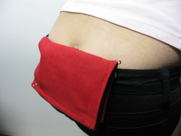
When your coin slot is exposed, this wearable hip-pack vibrates that area to make you aware of it. You decide to cover up, or let it all hang out.
The coin slot detector is a simple way to tackle the complicated modern problem low-rise jeans can cause. with this hip pack, now your coin slot itself is given the sensory power to alert you as to when it’s exposed. Both you and your coin slot decide what’s next.
Tech summary: Using a Lilypad Arduino, vibrating motor, and a photoresistor (measures the amount of light in your coin slot), you will make a wearable apparatus. When the photoresistor/your coin slot is covered, the hip-pack is at rest, when it/your coin slot is exposed, this triggers the vibrating motor to start vibrating & let the user know.
Step 1: Ingredients
Get your ingredients together!
for this project you’ll need:
-11.5 x 14.5 in fabric
-conductive thread
-lilypad Arduino
-vibrating motor
-1N4004 diode
-photoresistor (sometimes called photo cell)
-1.5 to 5 V step-up battery pack
-wire
-wire cutters
-thread
-snaps
-snap tool
-suspender clips
-plastic tubing
For prototyping (not pictured):
-Breadboard (you can buy this at Radio Shack)
-Arduino Diecimila
-USB cable
-Alligator clips (also buy these at Radio Shack)
-USB to Serial Converter
-female headers
-headers
Step 2: Prototype!
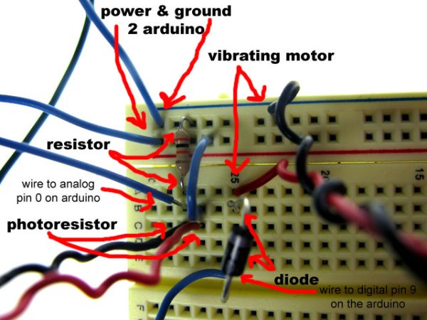
2. Connect wires to the breadboard- one wire into the blue rail for ground, and one into the red rail for power. Attach the power wire to the 5V input on the Diecimila Arduino and the ground wire to the Gnd input on the Diecimila Arduino.
2. Connect a 10Kohm resistor from the ground rail to the center of your breadboard on the same line. Then connect a wire in the hole next to it to the analog pin 0 on your Arduino.
3. Connect a wire from the power rail to the center of the breadboard.
4. Solder the photoresistor’s leads to longer wires to connect to the breadboard (about 4-5 inches).
5. Connect the photoresistor to ground in the breadboard by putting one wire next to the wire going to analog pin 0. Then connect the other wire to power by putting it in the hole next to the power wire you connected in step 3.
5. Connect a wire from the breadboard to digital pin 9 on the Arduino.
6. Then connect a 1N4004 diode in the hole next to it, and put it so that the ground side (the side with the grey stripe) is facing away from that wire.
7. Solder your vibrating motor’s leads to longer wires for prototyping.
8. Connect one of the vibrating motor’s wires to the hole next to the diode. connect the other vibrating motor lead to the ground rail.
9. Attach Arduino to computer via USB cable to power it.
10. Write the code in the following slide into the Arduino 0012 programming environment.
Step 3: Program in Arduino 0012
Open up Arduino 0012 on your computer. copy and paste the following code into your program window…then press the Verify button to make sure it works. Finally, click the Upload to Board button, to upload it to the Arduino to run. Once the program is uploaded, click the Serial Monitor button to see the values changing as you cover and uncover the photoresistor. When the values go above 500, the vibrating motor will vibrate!
/*Coin Slot Detector
by Amy Khoshbin
2008*/

int photoPin = 0; // Analog input pin that the photo resistor is attached to
int photoValue = 0; // value read from the photoresistor
int vibPin = 9;
boolean isVibrating = false;

void setup() {
// initialize serial communications at 9600 bps:
Serial.begin(9600);
pinMode(vibPin, OUTPUT);
}

void loop() {
photoValue = analogRead(photoPin); // read the pot value
Serial.println(photoValue); // print the pot value back to the debugger pane

vibrate();

delay(10); // wait 10 milliseconds before the next loop
}

void vibrate(){
//change the values greater than and less than to fit the sensitivity of the photoresistors you use

if(photoValue > 500 && isVibrating == false){
digitalWrite(vibPin, HIGH);
isVibrating = true;
}

if(photoValue < 500 && isVibrating == true) {
digitalWrite(vibPin, LOW);
isVibrating = false;
}

}
Step 4: If working, program the Lilypad Arduino
if your program runs, and you’re getting the photoresistor to get values into the Arduino and vibrate the vibrating motor, then you’re ready to move onto the Lilypad Arduino. To program this microcontroller, you need to use an USB to Serial converter.
Since the Lilypad doesn’t have headers soldered to them for easy prototyping or programming, I recommend using alligator clips.
First get female headers, then cut 4 off of the strip, and solders wires to each lead. Connect the female headers to the Gnd/RX/TX/Power headers on the Lilypad.
Then cut another 4 female headers and solder them to the USB to Serial Converter in the Gnd/RX/TX/Power holes. Attach the wires from the headers on the Lilypad Arduino to the USB to Serial Converter headers.
Attach the USB to Serial Converter to the computer via a USB cable. In the Arduino programming environment, go to the Tools menu, go to Board, and set it to Lilypad Arduino & set your Serial Port to the top one on the list. Then press the Upload to Board button in the Arduino programming environment, then press the Reset button on the Lilypad Arduino, and watch the program upload.
Once uploaded, we can start making the Coin Slot Detector!
Step 5: Cut fabric
Step 6: Pin & sew fabric edges
-orient fabric where 11.25″ is horizontal, and 14.25″ side is vertical.
-pin top and bottom edges of fabric by rolling the edge once, then again, and pin them down.
-sew top & bottom edges first.
-then pin right and left edges of fabric.
-sew right & left edges of fabric.
-fold fabric horizontally.picture 2:
-once right edges are sewn, fold fabric horizontally.
-sew the top 4 inches of the right edges together.picture 3:
-then roll the top edge of the fabric, pin it down.
-sew the top edge.picture 4:
the fabric piece is secured on the top half, but can be opened on the bottom half.(in the images below, the pins are pinned vertically, but as i learned after taking this photo, pin them horizontally, so you can sew over them without them getting in your way!)
Step 7: Snap the edges
Step 8: Sew battery pack
Step 9: Sew Lilypad Arduino
Step 10: Cut plastic tubing
measure .5″ from edge and cut plastic with a bandsaw or hand saw. sand with sandpaper to get rid of rough edges.
Step 11: Put vibrating motor in tube
see image below.
Step 12: Motorhead-ers
Step 13: Sew motor into place
sew left lead of motor to ground of Lilypad with the conductive thread attached to the motor’s lead.
Step 14: Bend diode legs to create hooks
bend diode legs to create hooks to sew to.
place diode .20″ from battery pack, motor, and Lilypad Arduino.
For more detail: Coin slot detector