Summary of Capture the image of a falling object using Arduino
This project uses an Arduino Uno and a light sensor to trigger a DSLR camera or flash when a falling object blocks a laser beam. The system detects the interruption in light via an LDR, processes the signal with the microcontroller, and activates a transistor switch to fire the flash or release the shutter at precise moments.
Parts used in the Falling Object Camera Trigger:
- Arduino Uno microcontroller board
- Laser pointer (light source)
- Cadmium sulphide photocell (LDR)
- Resistor R1
- NPN transistor
- 1.1kohm resistor
- Wireless flash trigger receiver with PC sync port
- PC sync cable
- Olympus E-520 camera
- Remote shutter release cable with 3.5mm stereo plug
- 12-pin connector
The aim of this project is to create a setup to capture the image of a falling object or any object in motion at a precise time using a DSLR and Arduino microcontroller. It can be done in many different ways, but the method I tried is illustrated below.
Figure 1: Schematic of the setup
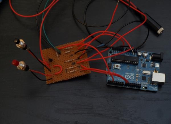
The idea is, when the object falling or moving blocks the light source from reaching light sensor the camera and/or the external flash unit is triggered. An Arduino Uno microcontroller board is used to measure the sensor values and send trigger signal to the camera/flash. With the microcontroller you can change the threshold value of the light sensor value and add precise dealy to the trigger signal. Here the light source is a simple laser pointer is used as a light source and a cadmium sulphide photocell acts as a light sensor. The wiring diagram is shown below,
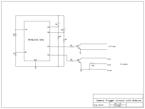
A bit of explanation on how this circuit works. The photocells or the Light Dependent Resistors (LDR) have a high resistance when there is no light, equivalent to open circuit. When light is shine on them their resistance reduces. The value of the resistance depends on how bright the light is. Initially when the light source is pointed to the LDR, it has a low resistance. The LDR and the resitor R1 act as a voltage divider circuit. The voltage drop across R1 is measured by the analog input terminal of the Arduino board. Ideally would have almost no resistance (0 ohms) when a bright light is focused on it. Which means the voltage drop measured across R1 would be ~5V. But depending on the intensity of the light source and the distance from the LDR, the LDR will have some low resistance value and hence the voltage across R1 (measured at A0 terminal) will be less than 5V. When a moving object cuts the beam of light the LDR value increases and hence the voltage across R1 drops. By comparing this value with an appropriate threshold value (which you can set to be somewhere between when the light is on the LDR and when it is blocked by the object), you can use the digital output lines to trigger the camera and/or flash by setting it to high.
The next step is to use the signal from digital output line of the arduino to trigger the camera and/or external flash unit. To trigger the external flash all you need to do is to short the two pins at the hot shoe connector (shown in the image below). I used a wireless flash trigger receiver which has a PC sync port to mount the flash unit. One end of the PC sync cable connects to the receiver unit and the other end connects to the collector and emitter terminals of a NPN transistor. The base of the transistor is connected to the one of the digital output lines of the Arduino board via a 1.1kohm resistor. This NPN transistor circuit acts as a switch which shorts the terminals of the PC sync cable and inturn firing the flash whenever the digital output line goes high.
The camera can be triggered in a similar way using the remote shutter release cable. Depending on the make and model the connector type and the pin configuration can change. The olympus E-520 uses a 12 pin port to interface with the computer for data/video transfer and remote shutter release. I got the pin diagram for the connector from the link here. I used a 3.5mm stereo plug to connect to the other end of the 12-pin connector (this way I can use the same cable to hook up to other circuits if needed). The digital output (pin D2) from Arduino is connected to a transistor switch circuit and the output of that is connected 3.5mm stereo female pin. The line going to pin 8 of the camera has a switch on it. This is the half release button. For the full release to work the half release need to be pressed. Since the camera menu does not work when the half release button is pressed, having a switch helps so that you can look at pictures or change settings while taking pictures. Flip in on to take pictures and flip if off the change the settings or look at pictures.
For more detail: Capture the image of a falling object using Arduino
- How does the circuit detect a moving object?
The LDR resistance increases when the laser beam is blocked, causing the voltage across resistor R1 to drop below a set threshold. - Can I change the sensitivity of the sensor?
Yes, you can adjust the threshold value for the light sensor readings within the Arduino code. - What component acts as the switch for the external flash?
An NPN transistor connected to a digital output line shorts the PC sync cable terminals to fire the flash. - How is the camera triggered using the Arduino?
A digital output line connects to a transistor switch that closes the half-release switch on the remote shutter cable. - Why is a switch included in the remote shutter cable setup?
The switch allows the user to look at pictures or change settings without holding the camera button down continuously. - What type of light source is recommended for this project?
A simple laser pointer is used as the light source to create a clear beam for the sensor to detect. - Does the distance between the laser and LDR affect the voltage?
Yes, the intensity of the light and distance from the LDR determine the resistance and resulting voltage drop. - Which pin on the Olympus E-520 controls the shutter release?
Pin 8 of the 12-pin connector interface corresponds to the half release button function.