Summary of How to Build a Vibration Motor Circuit
This project demonstrates building and controlling a vibration motor circuit using an Arduino. The vibration motor from Precision Microdrives operates at 2.5-3.8V and vibrates when powered. The project enhances control by using a 2N2222 transistor to amplify current, a diode for voltage spike protection, and a 0.1µF capacitor to absorb brush contact spikes. The Arduino drives the motor to vibrate once per minute. The setup ensures safe and efficient motor control, with potential for modifications to respond to events like noise or motion.
Parts used in the Vibration Motor Circuit Project:
- Arduino Board
- Precision Microdrives Shaftless Vibration Motor (Part number ROB-08449)
- 1N4001 Rectifying Diode
- 0.1 microfarad Ceramic Capacitor
- 1 kilo-ohm Resistor
- 33 Ohm Resistor
- 2N2222 NPN Transistor (or substitute with 2N3904)
- USB plug
- 2 AA Batteries (for simple motor powering, 3V)
This project will demonstrate the process of creating a circuit for a vibration motor.
A vibration motor is a motor that will vibrate once it receives enough power. It is a motor that truly vibrates.
It is highly effective for making objects vibrate. It has practical applications in various devices. For instance, cell phones are a common item that vibrates when receiving a call in vibration mode. A cellphone is a perfect illustration of an electronic device that includes a vibration motor. Another instance is a rumble pack in a gaming controller that vibrates, mimicking the movements in a game. One option for adding a rumble pack as an accessory is the Nintendo 64 controller, which included rumble packs to simulate gaming actions by vibrating. Another instance could be a toy like a furby that shakes when a person performs actions like petting or squeezing it, etc.
Vibration motor circuits possess numerous practical applications that can cater to various needs.
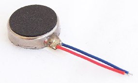
It is very easy to cause a vibration motor to vibrate. All that is required of us is to supply the necessary voltage to both terminals. A vibrating motor typically has 2 connectors, most commonly a red wire and a blue wire. Polarity is not relevant for motors.
We will utilize a Precision Microdrives vibration motor for our project. The motor requires a power source within the voltage range of 2.5-3.8V to operate.
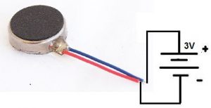
So if we connect 3 volts across its terminal, it will vibrate really well, such as shown below:
This is everything required to cause the vibration motor to vibrate. 2 AA batteries connected in series can supply 3 volts.
Nevertheless, our goal is to elevate the vibration motor circuit’s complexity and have it managed by a microcontroller like the arduino.
In this manner, we are able to exert greater dynamic influence on the vibration motor, enabling us to adjust its vibration frequency either on a scheduled basis or in response to specific events.
We will demonstrate how to connect this motor to an arduino in order to generate this kind of control.
In this project, our goal is to construct the circuit and program it to make the motor vibrate once per minute.
Parts Needed
- Board of Arduino
- Motor for creating vibrations
- 1N4001 Rectifying Diode
- 0.1 microfarad ceramic capacitor
- 1 kilo-ohm resistor
- 33 Ohm Resistor
- 2N2222 is an NPN transistor.
- USB plug
The vibration motor we will use is the shaftless vibration by Precision Microdrives. This can be obtained from Sparkfun at the following link: Sparkfun- Vibration Motor. The part number is ROB-08449.
The vibration mechanism and all moving parts are protected within the metallic housing encasing of the motor. For sturdiness and strength, the wires are reinforced and there is a 3M adhesive on its back surface.
The motor will vibrate considerably when supplied with 3V.
The datasheet for this vibration motor is at the following link: Precision Microdrives Vibration Motor Datasheet.
Almost any NPN transistor can be used to provide current amplification. If you do not have a 2N2222 NPN at hand, then substitute it for a 2N3904.
Vibration Motor Circuit
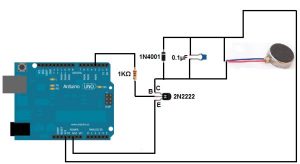
The vibration motor circuit we will build is shown below:
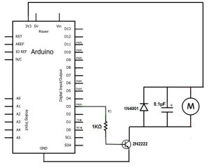
The schematic diagram for this circuit is:
When driving a motor with a microcontroller such as the arduino we have here, it is important to connect a diode reverse biased in parallel to the motor. This is also true when driving it with a motor controller or transistor. The diode acts as a surge protector against voltage spikes that the motor may produce. The windings of the motor notoriously produce voltage spikes as it rotates. Without the diode, these voltages could easily destroy your microcontroller, or motor controller IC or zap out a transistor. When simply powering the vibration motor directly with DC voltage, then no diode is necessary, which is why in the simply circuit we have above, we only use a voltage source.
The 0.1µF capacitor absorbs voltage spikes produced when the brushes, which are contacts connecting electric current to the motor windings, open and close.
The reason we use a transistor (a 2N2222) is because most microcontrollers have relatively weak current outputs, meaning they don’t output enough current to drive many different types of electronic devices. To make up for this weak current output, we use a transistor to provide current amplification. This is the purpose of this 2N2222 transistor we are using here. The vibration motor needs about 75mA of current to be driven. The transistor allows this and we can drive the motor. To make sure that too much current does not flow from the output of the transistor, we place a 1KΩ in series with the base of the transistor. This attenuates current to a reasonable amount so that too much current isn’t powering the motor. Remember that transistors usually provide about 100 times the amplification to the base current that enters through. If we don’t place a resistor at the base or at the output, too much current can be damaging to the motor. The 1KΩ resistor value isn’t precise. Any value can be used up to about 5KΩ or so.
We connect the output that the transistor will drive to the collector of the transistor. This is the motor as well as all components it needs in parallel with it for protection of the electronic circuitry.
Now that you understand why we use all the components which we do, let’s go to the code that allows the motor to vibrate every minute.
Vibration Motor Code
The code that vibrates the motor every minute is shown below:
Code to vibrate the motor every minute
const int motorPin = 3;
void setup()
{
pinMode(motorPin, OUTPUT);
}
void loop()
{
digitalWrite(motorPin, HIGH);
delay(1000);
digitalWrite(motorPin, LOW);
delay(59000);
}
The following code, again, vibrates the motor every minute for 1 second of a duration of time.
The first line of code declares that the motor is connected to arduino pin D3.
The second block of code sets the digital pin D3 as output. This output represents the motor.
The third block of code turns the motorPin HIGH and delays it 1000ms. This represents the motor turning on for 1 second. The second half of this block then turns the motorPin LOW and delays it 59,000ms. This represents the motor being shut after being on for a second and staying off for 59 seconds. So, in total, the motor turns on every minute for 1 second of time.
This is just one type of circuit that can be built. There are many variations which can be done, including the motor shaking when a certain action is done such as noise being detected or motion being detected. With a microcontroller such as an arduino, we have more control.
Also note that the 3.3V terminal on some arduinos may supply enough current to power the vibration motor. So you may be able to run this same circuit without the transistor setup. However, if you are powering multiple motors (in parallel), then a transistor may then be absolutely necessary.
For more detail: How to Build a Vibration Motor Circuit


